Linear vibration casting machine

A linear vibration, casting machine technology, applied to casting equipment, equipment for feeding molten metal into molds, manufacturing tools, etc., can solve problems such as blocked feeding pipes, inconvenient discharge of molten metal, and impact on quality

Pending Publication Date: 2021-05-18
谢剑波
View PDF0 Cites 0 Cited by
  • Summary
  • Abstract
  • Description
  • Claims
  • Application Information

AI Technical Summary

Problems solved by technology

[0003] The purpose of the present invention is to solve the problem that in the process of leading the molten metal to the mold in the prior art, the temperature of the molten metal will decrease and solidify gradually, and the molten metal in the feeding pipe is not convenient to be completely discharged, and finally the Condensation and solidification in the pipe will block the feeding pipe. At the same time, the molten metal will generate air bubbles during the transfer and flow process, which will lead to hollowing in the cast product and affect the quality. A linear vibration casting machine is proposed

Method used


Image

  • Linear vibration casting machine
  • Linear vibration casting machine
  • Linear vibration casting machine

Examples


Embodiment 1

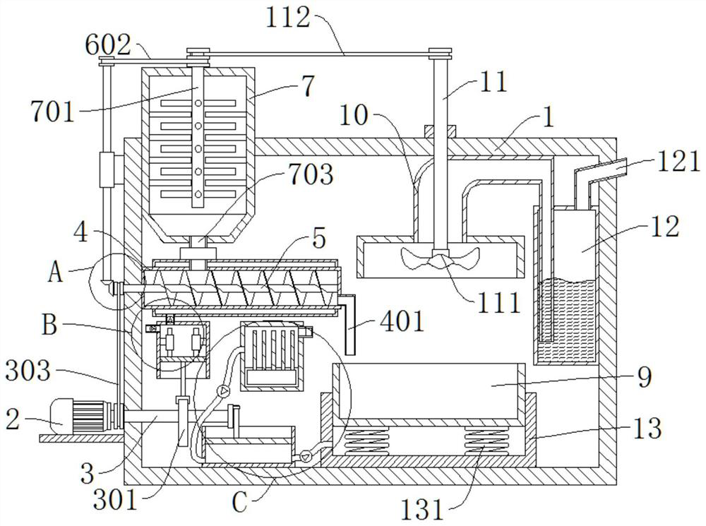
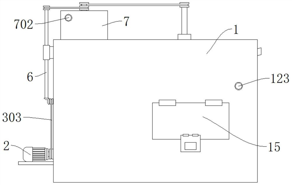
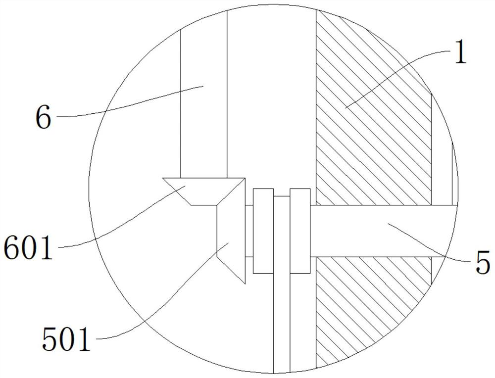
[0036] refer to Figure 1-5 , a linear vibration casting machine, comprising a box 1, a mixing box 7 is provided on the box 1, a stirring shaft 701 is arranged in the mixing box 7, a feeding pipe 702 is provided on the mixing box 7, and a stirring box 7 is provided in the box 1 The feed pipe 4 is connected with a pusher shaft 5 in rotation in the feed pipe 4, and the pusher shaft 5 is provided with a screw propulsion blade, and a feed pipe 703 is connected between the feed pipe 4 and the mixing box 7, and the feed pipe 703 A control valve is arranged on the top, a bevel gear 501 is arranged on the pushing shaft 5, a second rotating shaft 6 is rotatably connected to the side wall of the box body 1, and a driven gear 601 is arranged at the lower end of the second rotating shaft 6, and the driven gear 601 and the bevel gear 501, the second transmission belt 602 is connected between the second rotating shaft 6 and the stirring shaft 701, the side wall of the box body 1 is provided...

Embodiment 2

[0039] refer to figure 1 , 4 , a linear vibration casting machine, basically the same as Embodiment 1, furthermore, the transmission mechanism includes a cam 301, and the cam 301 is fixedly connected to the first rotating shaft 3, and the heating mechanism includes a first gas cylinder 8, and the first gas cylinder 8 A first piston 801 is slidably connected, and a first push rod 802 is fixedly connected to the lower end of the first piston 801. The end of the first push rod 802 away from the first piston 801 is slidably connected to the outer wall of the cam 301. Friction rod 803, friction ring 804 is provided in the first gas cylinder 8, friction rod 803 and friction ring 804 are slidingly connected, the first gas cylinder 8 is provided with a first air inlet pipe 805, the first gas cylinder 8 and the heating pipe 402 are connected with The first exhaust pipe 806, the first air intake pipe 805 and the first exhaust pipe 806 are all provided with check valves, the first exhau...

Embodiment 3

[0041] refer to figure 1 , 5 , a linear vibrating casting machine, which is basically the same as that of Embodiment 1, furthermore, a shock absorbing groove 13 is provided in the box body 1, the mold 9 is slidably connected in the shock absorbing groove 13, and a spring 131 is provided at the bottom of the mold 9, The end of the spring 131 away from the mold 9 is fixedly connected to the inner wall of the shock-absorbing groove 13. The setting of the shock-absorbing groove 13 and the spring 131 is convenient for shock absorption during the falling process of the casting material, so as to prevent the casting material from splashing when it falls on the mold 9. At the same time, the mold 9 vibrates under the pressure of the casting material, so that the casting material entering the mold 9 can be better and evenly laid in the mold 9, and the vibration of the mold 9 can greatly reduce the air bubbles inside the casting material and improve the quality of the finished product of...


PUM


Abstract

The invention discloses a linear vibration casting machine, and belongs to the field of metallurgical equipment. The linear vibration casting machine comprises a box body, a stirring box is arranged on the box body, a stirring shaft is arranged in the stirring box, a feeding pipe is arranged on the stirring box, a conveying pipe is arranged in the box body, a pushing rotating shaft is rotationally connected into the conveying pipe, a spiral propelling blade is arranged on the pushing rotating shaft, a guide pipe is connected between the conveying pipe and the stirring box, and a control valve is arranged on the guide pipe. According to the linear vibration casting machine, molten raw materials are conveniently stirred through the stirring box and are prevented from being solidified, the molten raw materials in the conveying pipe are conveniently pressurized and pushed through the pushing rotating shaft and the spiral propelling blade, bubbles in the raw materials are removed, meanwhile, the raw materials in the conveying pipe are conveniently and completely discharged, and a heating pipe, a transmission mechanism and a heating mechanism are arranged, so that the conveying pipe is conveniently heated, and the raw materials in the conveying pipe are prevented from being cooled and solidified in the transferring process.

Description

technical field [0001] The invention relates to the technical field of metallurgical equipment, in particular to a linear vibration casting machine. Background technique [0002] Casting is a method of melting gold and silver into a liquid state and casting them into utensils. It is one of the earliest gold and silver processing methods. The process of melting and smelting metals and their continued processing is casting. Casting machines are metal processing The commonly used equipment is used to shape and crystallize the liquid metal melted from the boiler into a solid state, and then roll it into products of different specifications through a rolling mill. In the process of leading the molten metal to the mold in the existing casting machine, the molten The temperature of the metal will drop and solidify gradually, and the molten metal in the feeding pipe is not easy to be completely discharged, and finally condenses and solidifies in the feeding pipe, blocking the feedin...

Claims


Application Information

Patent Timeline
Patent Type & Authority Applications(China)
IPC IPC(8): B22D35/04B22D35/06B22D27/08B22D27/04B22D45/00
CPCB22D27/04B22D27/08B22D35/04B22D35/06B22D45/005
Inventor 不公告发明人
Owner 谢剑波
Why Eureka
Try Eureka