
Mechanical and pneumatic combined dry anaerobic fermentation system and fermentation method

A dry anaerobic and fermentation system technology, applied in sterilization methods, bioreactors/fermenters for specific purposes, biochemical equipment and methods, etc. Methane emission, etc.

Active Publication Date: 2021-05-18
上海环境保护有限公司
View PDF8 Cites 6 Cited by
  • Summary
  • Abstract
  • Description
  • Claims
  • Application Information

AI Technical Summary

Problems solved by technology

[0003]The current dry anaerobic fermentation usually adopts a horizontal fermenter, which is fed from one end and discharged from the other end. Dry anaerobic fermentation is carried out in a horizontal fermenter It is usually divided into two stages. The first stage is the acid production stage. The new material enters the reaction tank, and more stirring is conducive to the mixing of materials, so that the crust layer (upper layer), supernatant layer (middle layer) and sediment layer ( Bottom layer) is completely mixed, and under suitable conditions and the action of microorganisms, the material is fermented to produce acid; the material after acid production enters the second half and begins to produce methane. Excessive stirring is not conducive to the production of methane by the material, but it also needs Proper agitation helps release methane produced
However, the interior of the existing horizontal fermenter is a single axial mechanical stirring shaft. First, the stirring degree of the two stages before and after fermentation is the same, which wastes energy, and is not conducive to the differential fermentation of the two stages before and after the fermentation, and the fermentation effect is poor; , there is a blind spot in the axial mechanical stirring shaft, especially it is difficult to eliminate the sediment at the bottom of the tank and the layer on the liquid surface of the tank, which leads to uneven mixing of materials and affects the fermentation efficiency. At the same time, the layer on the liquid surface will affect the emission of methane, which is not conducive to Gas collection, affecting fermentation efficiency and biogas utilization

Method used


Image

  • Mechanical and pneumatic combined dry anaerobic fermentation system and fermentation method
  • Mechanical and pneumatic combined dry anaerobic fermentation system and fermentation method
  • Mechanical and pneumatic combined dry anaerobic fermentation system and fermentation method

Examples


Embodiment Construction

[0039] The following will clearly and completely describe the technical solutions in the embodiments of the present invention with reference to the accompanying drawings in the embodiments of the present invention. Obviously, the described embodiments are only some, not all, embodiments of the present invention. Based on the embodiments of the present invention, all other embodiments obtained by persons of ordinary skill in the art without making creative efforts belong to the protection scope of the present invention.

[0040] In the following description, many specific details are set forth in order to fully understand the present invention, but the present invention can also be implemented in other ways different from those described here, therefore, the protection scope of the present invention is not limited by the specific implementation disclosed below. Example limitations.

[0041] In describing the present invention, it should be understood that the terms "center", "l...


PUM


Abstract

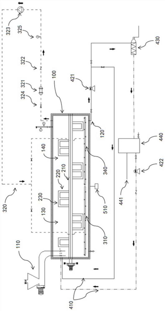
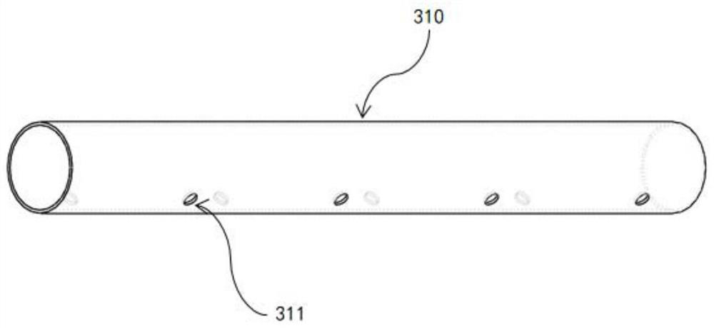
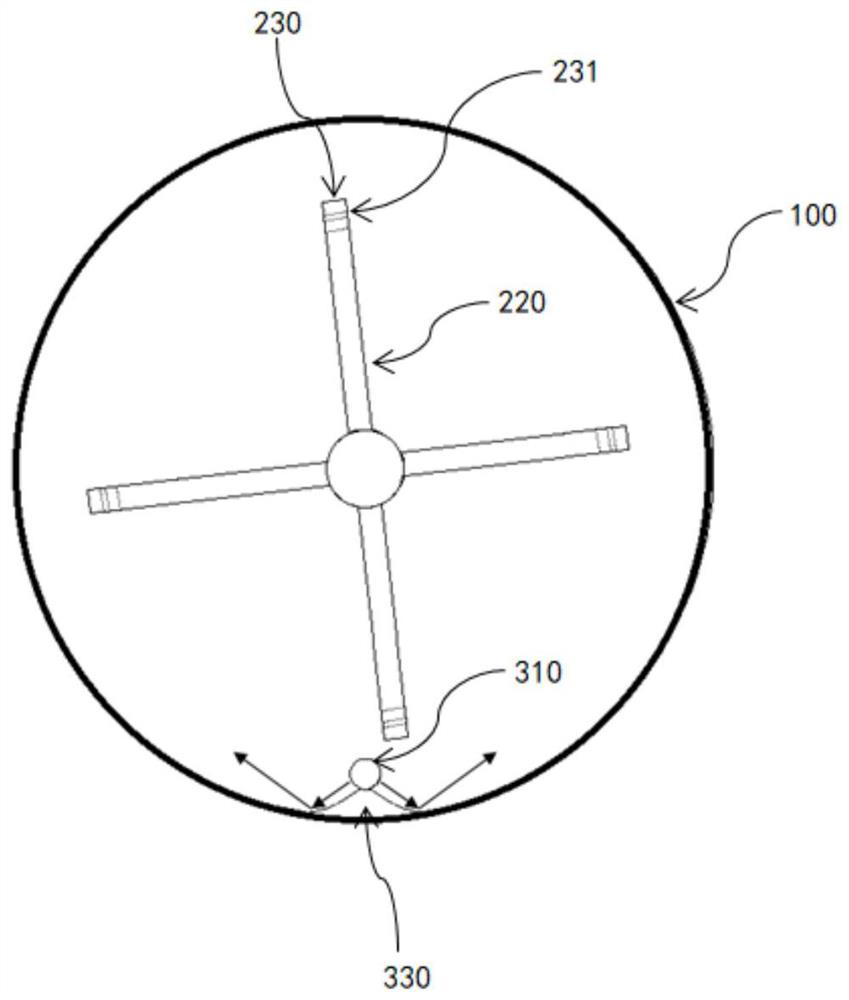
The invention discloses a mechanical and pneumatic combined dry anaerobic fermentation system. The system comprises a horizontal fermentation tank, a mechanical stirring assembly and a pneumatic stirring assembly, wherein the mechanical stirring assembly comprises a stirring shaft arranged in the axial direction of the horizontal fermentation tank and a plurality of blades arranged on the stirring shaft; the pneumatic stirring assembly comprises a first pneumatic pipe, a second pneumatic pipe and an air supply pipeline connected with the first pneumatic pipe and the second pneumatic pipe, and the first pneumatic pipe and the second pneumatic pipe are sequentially arranged in the axial direction of the horizontal fermentation tank. Through combination of the mechanical stirring assembly and the pneumatic stirring assembly, energy consumption of mechanical stirring is reduced, gas generated through fermentation is used for stirring, energy is saved, the first pneumatic pipe corresponds to the material acid production stage, the second pneumatic pipe corresponds to the material methane production stage, materials in the two stages are stirred in a differentiated mode, the stirring requirements of the materials in different stages are met, and efficient anaerobic fermentation of the fermented materials is facilitated.

Description

technical field [0001] The invention relates to the technical field of dry anaerobic fermentation, in particular to a dry anaerobic fermentation system and fermentation method combined with mechanical and pneumatic. Background technique [0002] Dry anaerobic fermentation is an organic biowaste technology with low requirements for raw material pretreatment, low energy consumption, simple system, and convenient management. application prospects. [0003] The current dry anaerobic fermentation usually adopts a horizontal fermenter, which is fed from one end and discharged from the other end. The dry anaerobic fermentation is usually divided into two stages in the horizontal fermenter. The first stage is the acid production stage, and the new stage The material enters the reaction tank, more stirring is conducive to the mixing of materials, so that the crust layer (upper layer), supernatant layer (middle layer) and sediment layer (bottom layer) of the straw fermentation produc...

Claims


Application Information

Patent Timeline
IPC IPC(8): C12M1/107C12M1/38C12M1/34C12M1/16C12M1/04C12M1/02
CPCC12M21/04C12M21/16C12M23/34C12M23/36C12M27/06C12M27/22C12M29/06C12M29/18C12M29/24C12M37/04C12M41/12C12M41/00Y02E50/30
Inventor 陈静洪祖喜王国良张心良贾磊徐文倩王建翔吴志平王振旗
Owner 上海环境保护有限公司
Learn More