
Construction method of cast-in-place drainage ditch

A construction method and drainage ditch technology, applied in the field of drainage engineering, can solve the problems of narrow construction site, complex construction technology, and large impact on current traffic.

Active Publication Date: 2021-05-18
安徽仁成建设工程有限公司
View PDF7 Cites 3 Cited by
  • Summary
  • Abstract
  • Description
  • Claims
  • Application Information

AI Technical Summary

Problems solved by technology

[0003] The drainage ditch is one of the most effective facilities for collecting and discharging rainwater in the city. When the drainage ditch is constructed in the city, the current road has already been formed, the construction site is narrow, and the requirements for safe and civilized construction are high. The traditional drainage ditch construction has an impact on the current traffic. It is relatively large, and the construction period for installing and removing formwork is long, and it is difficult for operators to control the construction process. The construction often fails to meet the design requirements, and the phenomenon of rectification and rework frequently occurs in the later stage
[0004] In the related technology, the canal forming machine is used as the drainage ditch construction equipment, but due to the narrow construction site of the urban drainage ditch and the short drainage ditch, the canal forming machine has high requirements for the construction site conditions, and it is difficult to meet the construction requirements of the urban drainage ditch, while the traditional The construction process is complicated and the construction efficiency is low

Method used


Image

  • Construction method of cast-in-place drainage ditch
  • Construction method of cast-in-place drainage ditch
  • Construction method of cast-in-place drainage ditch

Examples


Embodiment Construction

[0044] The following is attached Figure 1-4 The application is described in further detail.

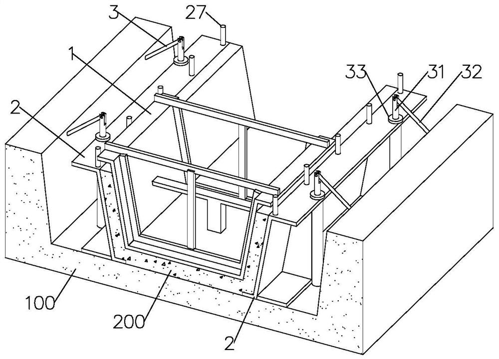
[0045] The embodiment of the application discloses a construction method of a cast-in-place drainage ditch. refer to figure 1 In this construction method, the structure of the shaped drainage ditch 200 is poured by using the pouring mold to pour the construction in the trench. The shaped drainage ditch 200 is the main body of the drainage ditch. The type is selected according to the design requirements, and the opening width at the bottom can be selected to be different. The variable U-shaped groove can also choose a trapezoidal groove whose opening width gradually increases upwards. In this embodiment, a trapezoidal groove is selected as an example, and a groove with a trapezoidal cross-section is also excavated on the groove foundation 100 .

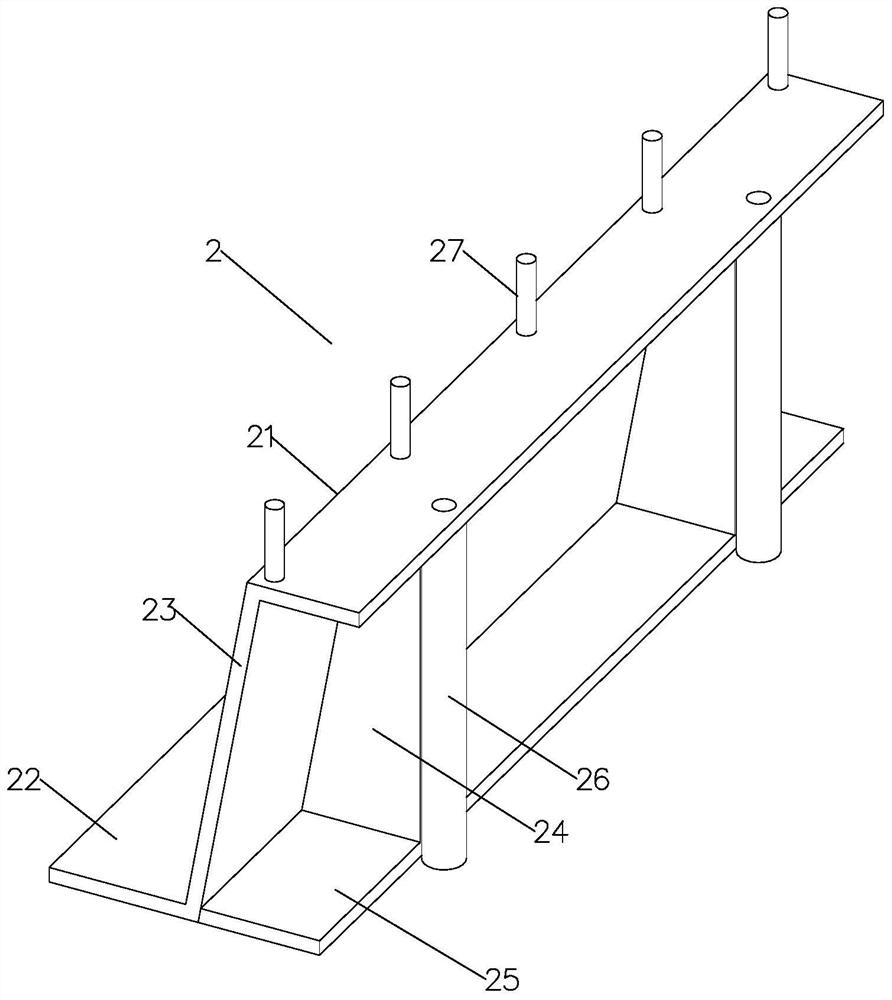
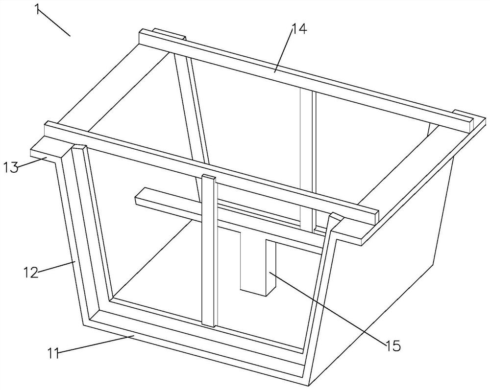
[0046] refer to figure 1 , the pouring mold includes a bottom mold and a pressure mold 1, wherein the bottom mold is placed in the trench...


PUM


Abstract

The invention relates to the technical field of drainage engineering, and particularly relates to a construction method of a cast-in-place drainage ditch. The construction method comprises the following steps that a groove is excavated; the groove is leveled; a bottom die is installed, the bottom die is divided into a left part and a right part, the two parts of the bottom die are fixed to the bottom of the groove, and the bottom of the groove supports the bottom surfaces of the two parts of the bottom die; concrete is poured, specifically, the concrete is poured between the two parts of the bottom die, and the concrete flows downwards along the side walls of the two parts of the bottom die and is converged between the two parts of the bottom die; a pressing die is installed, specifically, the pressing die squeezes the concrete at the bottom of the bottom die, so that the concrete is used for filling between the side wall of the bottom die and the side wall of the pressing die, and shaping is carried out; the die is removed, specifically, after a drainage ditch main body starts to be hardened, the pressing die is removed, and after maintenance is completed, the bottom die is removed; and the groove is backfilled, specifically, after the die is removed, slurry supplementing or sand and stone backfilling is carried out at the bottom of the drainage ditch main body, and then the groove is backfilled and compacted. According to the construction method, the construction efficiency of the urban cast-in-place drainage ditch is improved, and the construction steps are simplified.

Description

technical field [0001] The application relates to the field of drainage engineering, in particular to a construction method of cast-in-place drainage ditches. Background technique [0002] The urban drainage system is an engineering facility system that treats and removes urban sewage and rainwater. It is an integral part of urban public facilities. Urban drainage system planning is an integral part of urban overall planning. The urban drainage system usually consists of drainage pipes and sewage treatment plants. In the case of sewage and rainwater separation system, the sewage is collected by the drainage pipes, sent to the sewage treatment, discharged into the water body or recycled; the rainwater runoff is collected by the drainage pipes , discharged into the nearest water body. The urban drainage system is very critical in the daily operation of the city and when it encounters heavy precipitation. At present, with the construction of urbanization and the improvement o...

Claims


Application Information

Patent Timeline
Patent Type & Authority Applications(China)
IPC IPC(8): E03F3/04E03F3/06
CPCE03F3/04E03F3/06Y02A30/60
Inventor 余伟尹佳李玉龙杨聪聪吴雪桂笑娜吴连为
Owner 安徽仁成建设工程有限公司
Learn More