
Ventilation energy-saving equipment for green building

A technology for energy-saving equipment and green buildings, applied in space heating and ventilation details, ventilation systems, mechanical equipment, etc., can solve problems such as inability to meet the needs of indoor ventilation, high dependence on electric energy, and poor use of natural wind

Active Publication Date: 2021-05-18
CHINA NAT CHEM ENG HEAVY MECHANIZED CORP
View PDF4 Cites 4 Cited by
  • Summary
  • Abstract
  • Description
  • Claims
  • Application Information

AI Technical Summary

Problems solved by technology

[0003] However, most of the air inlets of the existing ventilation devices are fixed and can only be set in a specific direction. Due to the influence of the changing factors of the natural wind direction, the existing ventilation devices have a poor utilization effect on the natural wind, and even It cannot meet the needs of indoor ventilation; moreover, the existing ventilation device is very dependent on electric energy, and the long-term operation of the ventilation device will cause a large load on the supply of the urban power grid, failing to achieve the purpose of energy saving

Method used


Image

  • Ventilation energy-saving equipment for green building
  • Ventilation energy-saving equipment for green building
  • Ventilation energy-saving equipment for green building

Examples


Embodiment Construction

[0032] The following will clearly and completely describe the technical solutions in the embodiments of the present invention with reference to the accompanying drawings in the embodiments of the present invention. Obviously, the described embodiments are only some, not all, embodiments of the present invention. Based on the embodiments of the present invention, all other embodiments obtained by persons of ordinary skill in the art without making creative efforts belong to the protection scope of the present invention.

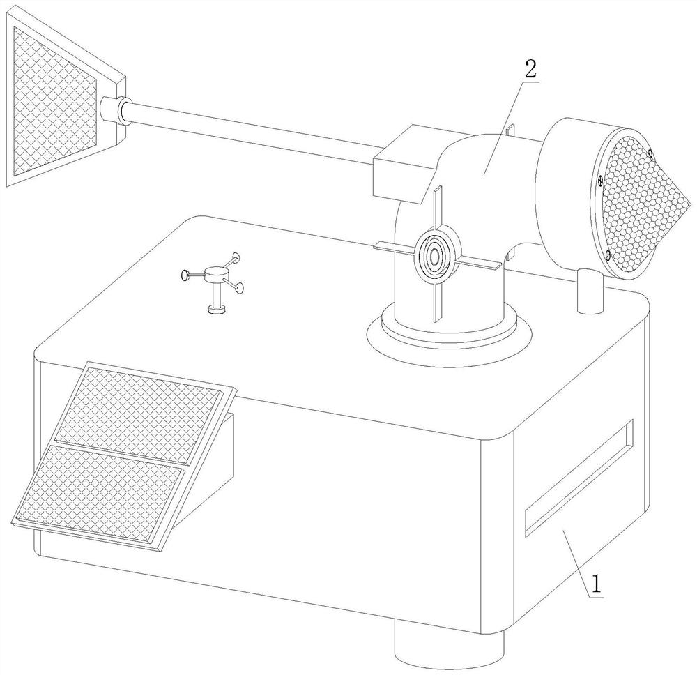
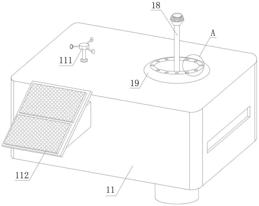
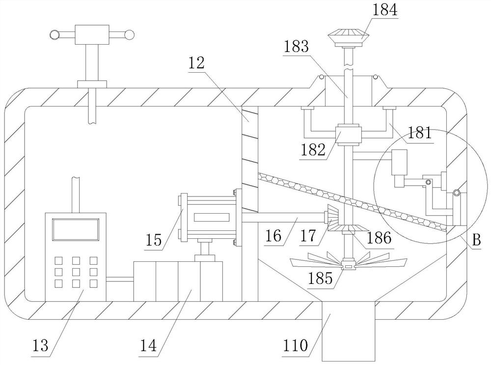
[0033] see Figure 1-4 , a ventilation and energy-saving equipment for green buildings, including a base 1 and a ventilation device 2, the ventilation device 2 is installed on the upper end of the base 1, the base 1 includes a housing 11, a partition 12, a microcomputer controller 13, a storage battery 14, Motor 15, power transmission shaft 16, bevel gear one 17, blower assembly 18 and raised round platform 19, the inside of housing 11 is provided with integra...


PUM


Abstract

The invention discloses ventilation energy-saving equipment for a green building. The ventilation energy-saving equipment for the green building comprises a base and a ventilation device, the top of a shell corresponding to a second cavity of the base is provided with a communicating protruding circular truncated cone, the outer side of a top port of the protruding circular truncated cone is annularly provided with clamping grooves for clamping and installing small steel balls, and a ventilation pipe is clamped and sleeved into the protruding circular truncated cone through a limiting chuck; an air adjusting plate is arranged on the outer wall of one end, away from an air inlet barrel, of the ventilation pipe through cooperation of a protruding block and a transverse rod, the air adjusting plate is perpendicular to a top plate of the shell, the air adjusting plate is blown by strong wind to drive the ventilation pipe to rotate at the top end of the protruding circular truncated cone through the transverse rod in windy weather according to the lever principle, and the air inlet barrel is aligned to the air coming direction; the consistency of the air inlet barrel and the wind coming direction is always ensured like a wind indicator for predicting the wind direction, natural wind is fully utilized, manual adjustment is not needed, and convenience and practicability are achieved.

Description

technical field [0001] The invention relates to the technical field of environmental protection and energy-saving equipment, in particular to ventilation and energy-saving equipment for green buildings. Background technique [0002] A green building is a high-quality building that saves resources, protects the environment, reduces pollution, provides people with healthy, applicable, and efficient use of space, and maximizes the harmonious coexistence of man and nature within the entire life cycle. The evaluation of green buildings should follow local conditions Based on the principles of climate, environment, resources, economy, and culture in the area where the building is located, comprehensively evaluate the performance of the building in terms of safety and durability, health and comfort, convenience of life, resource conservation, and livable environment during the entire life cycle of the building. . To maintain indoor ventilation in green buildings, ventilation devic...

Claims


Application Information

Patent Timeline
Patent Type & Authority Applications(China)
IPC IPC(8): F24F7/007F24F7/003F24F8/108F24F13/10F24F13/28F24F13/32H02J7/35
CPCF24F7/007F24F13/10F24F13/28F24F13/32H02J7/35
Inventor 王瑶
Owner CHINA NAT CHEM ENG HEAVY MECHANIZED CORP
Learn More