High-efficiency heat regenerator with inner layer coated with film

A regenerator and film coating technology, which is used in superheaters, refrigeration components, refrigerators, etc., can solve problems such as electrochemical corrosion, increasing the length of the return pipe, and adversely controlling the noise of the refrigeration system.

Pending Publication Date: 2021-05-18
CHANGHONG MEILING CO LTD
View PDF0 Cites 0 Cited by
  • Summary
  • Abstract
  • Description
  • Claims
  • Application Information

AI Technical Summary

Problems solved by technology

The air return pipe is mostly made of aluminum pipes. Because of the low surface temperature, it is easy to absorb the surrounding moisture. The capillary pipes are copper pipes. Electrochemical corrosion is prone to occur between the copper and aluminum pipes in a humid environment. Corrosion of the aluminum pipes will easily lead to refrigeration in the refrigeration system agent leak
[0004] The capillary is longer than the return pipe. The traditional design is to coil the non-parallel segment capillary at the inle

Method used


Image

  • High-efficiency heat regenerator with inner layer coated with film
  • High-efficiency heat regenerator with inner layer coated with film
  • High-efficiency heat regenerator with inner layer coated with film

Examples


Embodiment 1

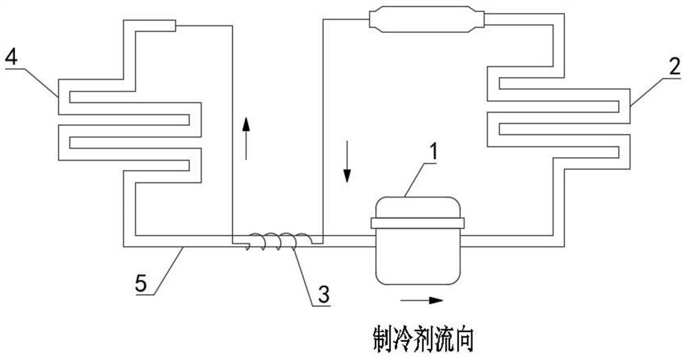
[0030] The present invention is a high-efficiency regenerator covered with an inner layer, a capillary 3 and a return air pipe 5; the capillary 3 includes a capillary inlet section 301 and a capillary outlet section 302; the return air pipe 5 includes a return air pipe inlet section 501 and a return air pipe outlet section 502; The outlet section 502 of the air return pipe is sequentially connected with a compressor 1, a condenser 2, a capillary tube 3 and an evaporator 4; the outlet section of the evaporator 4 is connected with the inlet section 501 of the air return pipe to form a circulating refrigeration system;

[0031] The circulating refrigeration system is filled with refrigerant 6; the refrigerant 6 flows out from the outlet of the compressor, and flows through the condenser 2, capillary 3, evaporator 4 and return pipe 5 in sequence, and finally flows into the inlet of the compressor 1; the capillary 3 is Reciprocating folding structure; the capillary 3 is evenly distr...

Embodiment 2

[0037] The present invention is a high-efficiency regenerator covered with an inner layer, a capillary 3 and a return air pipe 5; the capillary 3 includes a capillary inlet section 301 and a capillary outlet section 302; the return air pipe 5 includes a return air pipe inlet section 501 and a return air pipe outlet section 502; The outlet section 502 of the air return pipe is sequentially connected with a compressor 1, a condenser 2, a capillary tube 3 and an evaporator 4; the outlet section of the evaporator 4 is connected with the inlet section 501 of the air return pipe to form a circulating refrigeration system;

[0038] The circulating refrigeration system is filled with refrigerant 6; the refrigerant 6 flows out from the outlet of the compressor, and flows through the condenser 2, capillary 3, evaporator 4 and return pipe 5 in sequence, and finally flows into the inlet of the compressor 1; the capillary 3 is Reciprocating folding structure; the capillary 3 is evenly distr...

Embodiment 3

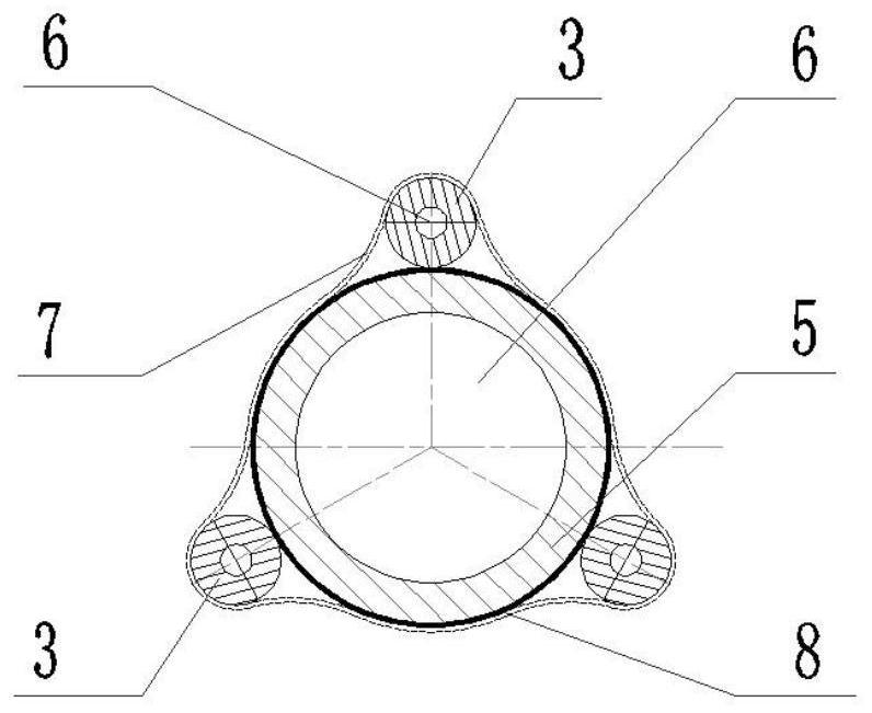
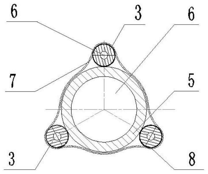
[0044] see Figure 1-3 As shown, the present invention is a high-efficiency regenerator with an inner film covering, including a capillary 3 and a return air pipe 5; the capillary 3 includes a capillary inlet section 301 and a capillary outlet section 302; the return air pipe 5 includes a return air pipe inlet section 501 and a return air pipe exit section 502;

[0045] The outlet section 502 of the air return pipe is sequentially connected with the compressor 1, the condenser 2, the capillary tube 3 and the evaporator 4; the outlet section of the evaporator 4 is connected with the inlet section 501 of the air return pipe to form a circulating refrigeration system; the interior of the circulating refrigeration system is filled with refrigerant 6. The refrigerant 6 flows out from the outlet of the compressor, and flows through the condenser 2, the capillary 3, the evaporator 4 and the return pipe 5 in sequence, and finally flows into the inlet of the compressor 1;

[0046]The ...


PUM


Abstract

The invention discloses a high-efficiency heat regenerator with an inner layer coated with a film, and relates to the technical field of vapor compression type refrigerating systems. The device comprises a capillary tube and an air return tube. The capillary tube comprises a capillary tube inlet section and a capillary tube outlet section. The air return tube comprises an air return tube inlet section and an air return tube outlet section. The air return tube outlet section is sequentially connected with a compressor, a condenser, the capillary tube and an evaporator. The outlet section of the evaporator is connected with the air return tube inlet section to form a circulating refrigeration system. The circulating refrigeration system is filled with a refrigerant. The refrigerant flows out from the outlet end of the compressor, sequentially flows through the condenser, the capillary tube, the evaporator and the air return tube and finally flows into the inlet end of the compressor. The outer surface of the air return tube is covered with a plastic film, the risk of electrochemical corrosion between the air return tube and the capillary tube is reduced, and the capillary tube is arranged to be of a reciprocating folding structure, so that the heat exchange efficiency of the heat regenerator is improved.

Description

technical field [0001] The invention belongs to the technical field of vapor compression refrigeration systems, and in particular relates to an inner film-coated high-efficiency regenerator. Background technique [0002] The vapor compression refrigeration system is a closed circuit. The compressor drives the refrigerant to circulate in the condenser, capillary, evaporator, return pipe and other components in order to realize the transfer of heat. The parallel heat exchange part of the return pipe and the capillary is called refrigeration. The regenerator of the system, the refrigerant in the regenerator undergoes countercurrent heat exchange. Through countercurrent heat exchange, on the one hand, the subcooling degree of the refrigerant in the capillary tube is reduced, and on the other hand, under the heating effect of the capillary tube, the temperature of the return air pipe It is beneficial to improve the efficiency of the refrigeration system. [0003] Refrigerators a...

Claims


Application Information

Patent Timeline
IPC IPC(8): F25B40/06F25B41/37
CPCF25B40/06
Inventor 荆嵩李清松李艳革
Owner CHANGHONG MEILING CO LTD
Why Eureka
Try Eureka