Sampling device for SO3 in stationary pollution source flue gas

A technology for fixing pollution sources and sampling devices, applied in sampling devices, measuring devices, sampling, etc., can solve the problems of insufficient portability, difficult cleaning, and many connecting pipelines

Pending Publication Date: 2021-05-18
CHINESE RES ACAD OF ENVIRONMENTAL SCI
View PDF0 Cites 1 Cited by
  • Summary
  • Abstract
  • Description
  • Claims
  • Application Information

AI Technical Summary

Problems solved by technology

[0006] First, in the controlled condensation method, the particle filter membrane is placed behind the sampling gun and outside the flue, which belongs to the external filtration method. This method will cause a large amount of particles to adhere to the sampling gun, and it is very difficult to clean after sampling; the isopropanol absorption method Because it is suitable for sulfuric acid industrial exhaust gas, no filter membrane is required, so it is not suitable for dusty flue gas
[0007] Second, the degree of equipment integration is low and the portability is insufficient
Whether it is DL / T 1990-2019, GB / T38685-2020, EPA8 or EPA8A, it is necessary to carry multiple absorption bottles for sampling, and there are many connecting pipelines between components, and it is necessary to carry an ice bath or temperature-controlled water bath , equipped with ice water or hot water, especially the imported equipment produced according to the EPA8 or EPA8A standard is bulky and heavy, and usually the flue gas outlets of enterprises are located at a higher position, which causes inconvenience in on-site transportation and long time for instrument preparation
[0008] Third, on-site operations are cumbersome
low efficiency

Method used


Image

  • Sampling device for SO3 in stationary pollution source flue gas
  • Sampling device for SO3 in stationary pollution source flue gas

Examples


Embodiment Construction

[0034] The following description and drawings sufficiently illustrate specific embodiments of the invention to enable those skilled in the art to practice them. Other embodiments may incorporate structural, logical, electrical, process, and other changes. The examples merely represent possible variations. Individual components and functions are optional unless explicitly required, and the order of operations may vary. Portions and features of some embodiments may be included in or substituted for those of other embodiments.

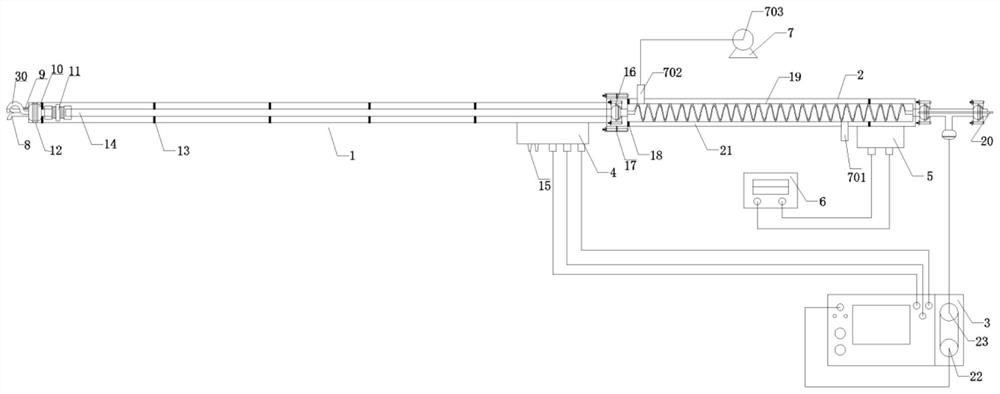
[0035] Such as figure 1 As shown, in some illustrative embodiments, there is provided a SO in the flue gas of a stationary pollution source 3 The sampling device includes: front section bong 1, back section bong 2, sampling host 3, sampling head front section bong heater 4, back section bong heater 5, back section bong temperature controller 6, air cooling device 7. Pitot tube 8, intake smoke temperature sensor 9, quartz filter 10, connecting pipe fit...


PUM


Abstract

The invention provides a sampling device for SO3 in stationary pollution source flue gas. The sampling device comprises a front-section smoke gun, a rear-section smoke gun, a sampling main machine, a sampling head, a front-section smoke gun heater, a rear-section smoke gun heater, an air cooling device, a pitot tube, an air inlet smoke temperature sensor, a quartz filter, a quartz glass lining tube, a quartz condensation tube and a condensation tube outlet smoke temperature sensor. According to the invention, all the components are modularized, so that on-site connection / disassembly is simpler and more convenient, and carrying is convenient; when the SO3 emission concentration is accurately tested, the number of equipment carried during on-site monitoring is reduced, and the complexity of on-site instrument connection and chemical reagent configuration and recovery operation is reduced, so that the sampling efficiency is improved; and flue gas sampling under different temperature conditions is realized. According to the invention, the filterable particulate matters are captured at the foremost end of the sampling device in a manner of preposing the quartz filter, the smoke gun does not need to be cleaned, and only the sampling nozzle needs to be cleaned, so that the cleaning operation after sampling is simplified.

Description

technical field [0001] This invention belongs to SO 3 Pollutant sampling and monitoring technical field, especially related to a kind of SO in the flue gas of fixed pollution source 3 sampling device. Background technique [0002] SO 3 It is an unconventional pollutant in the flue gas emitted by stationary sources. It usually exists in the flue gas of stationary pollution sources in the form of aerosols and is extremely difficult to remove. [0003] In my country, SO in flue gas emitted from stationary sources 2 Remarkable achievements have been made in emission control, but for SO 3 Governance and removal are still in their infancy. SO 3 It will increase the acid dew point of flue gas, cause blue smoke plume, corrode equipment, and SO 3 than SO 2 The toxicity of SO is more than ten times higher than that of SO 3 Exists mostly in the form of aerosols in flue gas and the atmosphere, is one of the main pollutants causing environmental acidification, and is an importan...

Claims


Application Information

Patent Timeline
Patent Type & Authority Applications(China)
IPC IPC(8): G01N1/22G01N15/06
CPCG01N1/2202G01N1/2205G01N1/2247G01N1/2258G01N15/06G01N2001/225
Inventor 张辰杨丽刘宇田刚龙红艳束韫崔宇韬朱金伟王洪昌陈宇石应杰
Owner CHINESE RES ACAD OF ENVIRONMENTAL SCI
Why Eureka
Try Eureka