High-integration-level pulse testing device
A pulse test, highly integrated technology, applied in the direction of measuring devices, measuring electricity, measuring electrical variables, etc., can solve problems such as testing difficulties
- Summary
- Abstract
- Description
- Claims
- Application Information
AI Technical Summary
Problems solved by technology
Method used
Image
Examples
Embodiment 1
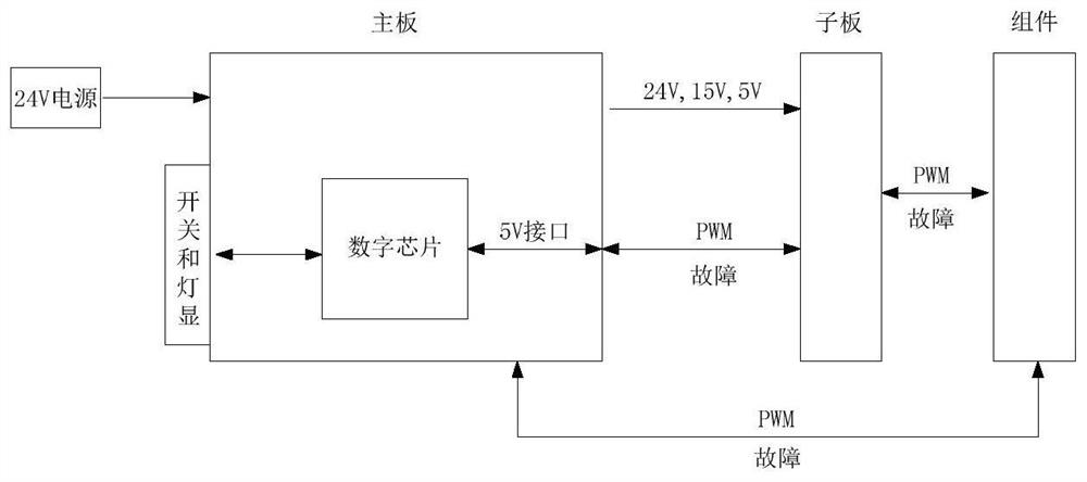
[0057] see figure 2, the highly integrated pulse test device of this embodiment includes: a switch combination unit, a level conversion device and a control circuit:
[0058] The level conversion device is used to convert the external DC power supply of a single voltage into a plurality of output power interfaces corresponding to different voltages, respectively supplying power to the switch combination unit and the control circuit;
[0059] A switch combination unit, used to input control circuits by selecting different switch states;
[0060] The control circuit is used to select, generate and output corresponding test pulses according to different input switch states, so as to perform low voltage logic, dead time, minimum pulse width, chopping and short circuit tests. During implementation, the test pulse generated by the control circuit is transmitted to the daughter board through an electrically connected PWM (Pulse width modulation, pulse width modulation) transmission...
Embodiment 2
[0081] see Figure 7 , the structure of the highly integrated pulse testing device of this embodiment is basically the same as that of Embodiment 1, with slightly different details.
[0082] The test device supplies power to the main board (control circuit + level shifting circuit) through a 24V external power supply. There are multiple level shifting devices on the main board to change the 24V power supply into three commonly used levels of 24V, 15V, and 5V for components. The board provides power, and the fault interface can also adapt to these 3 different fault levels. All PWM transmission ports and fault signal receiving ports (which can receive output signals in normal conditions and fault signals in fault conditions) have two modes: optical and electrical. The transmission circuits of electrical signals and optical signals are 12 channels, of which 6 channels are PWM transmission interface, 6 channels are fault feedback interfaces. And there is a switch combination uni...
PUM
 Abstract
Description
Claims
Application Information
 - R&D
- Intellectual Property
- Life Sciences
- Materials
- Tech Scout
- Unparalleled Data Quality
- Higher Quality Content
- 60% Fewer Hallucinations
Browse by: Latest US Patents, China's latest patents, Technical Efficacy Thesaurus, Application Domain, Technology Topic, Popular Technical Reports.
© 2025 PatSnap. All rights reserved.Legal|Privacy policy|Modern Slavery Act Transparency Statement|Sitemap|About US| Contact US: help@patsnap.com


