
Intensive pouring bus duct assembly

A busway, intensive technology, applied in the field of busway, can solve the problems of large space occupied by busway, poor applicability, and low fire performance

Pending Publication Date: 2021-05-18
珠海顺鑫电气设备有限公司
View PDF0 Cites 0 Cited by
  • Summary
  • Abstract
  • Description
  • Claims
  • Application Information

AI Technical Summary

Problems solved by technology

[0004] The purpose of the present invention is to overcome the shortcomings of the above-mentioned prior art, and provide a dense cast busway assembly, which solves the problems of large space occupied by the busway and low fireproof performance in the prior art, and overcomes the high fire protection requirements. Defects of poor applicability in indoor places

Method used


Image

  • Intensive pouring bus duct assembly
  • Intensive pouring bus duct assembly
  • Intensive pouring bus duct assembly

Examples


Embodiment 1

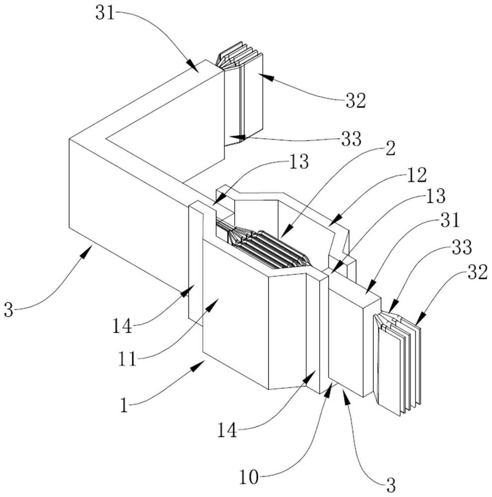
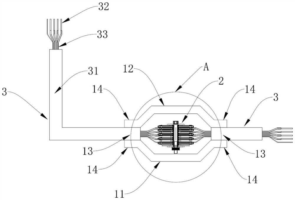
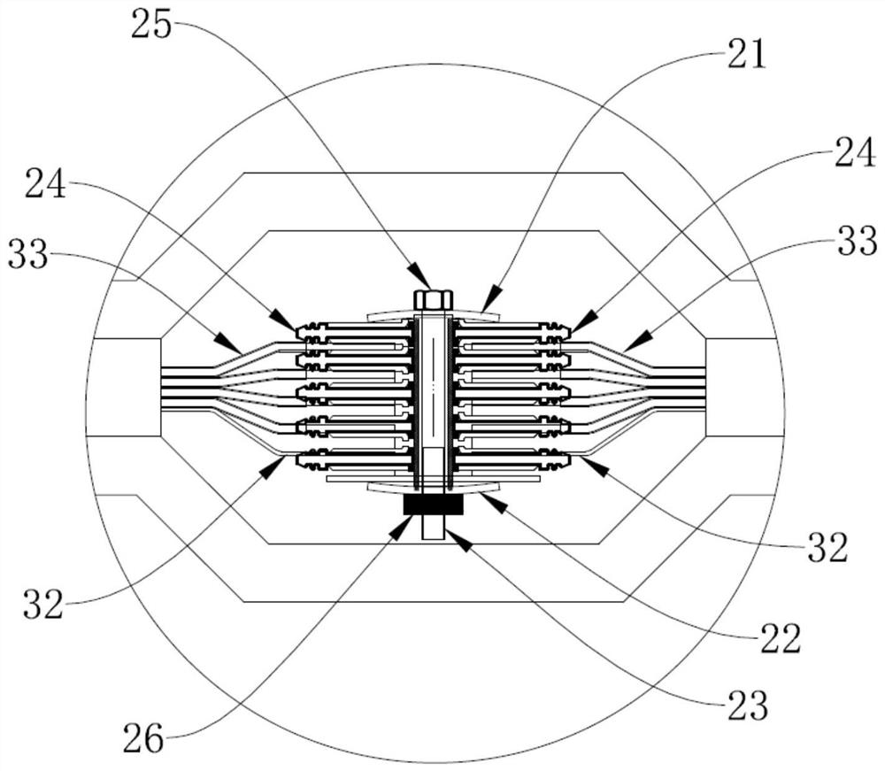
[0024] refer to figure 1 with figure 2 , Embodiment 1 provides a dense cast bus duct assembly, including a connecting outer box 1, a splicing unit 2 and several bus duct units 3, the bus duct unit 3 includes a housing 31 and several copper bars 32, the copper bars 32 The surface is provided with a film-coated insulating layer 33, and several copper bars 32 are stacked and penetrated in the inner cavity of the housing 31. Both ends of the copper bars 32 protrude from the inner cavity of the housing 31. The copper bars 32 are connected through the splicing unit 2, and the connecting outer box 1 is arranged outside the exposed connection part of the two copper bars 32, and the connecting outer box 1 encloses a storage space, and the refractory castable material is cast in the storage space.

[0025] It should be noted that each bus duct unit 3 can be set in different lengths and shapes in order to adapt to various installation environments. Section by section bus duct units 3 a...

Embodiment approach

[0028] As another embodiment, the refractory casting material includes the following components: 55-65 parts of novolac epoxy resin, 10-16 parts of curing agent, 20-25 parts of quartz sand, and 7-14 parts of vermiculite. Wherein: the configuration method of pouring material comprises the following steps: Step 1, putting the novolac epoxy resin, curing agent, quartz sand, and vermiculite of corresponding weight parts into the vacuum agitator; Step 2, setting the pressure of the vacuum agitator to 1.0MPa , and stirred for 15 minutes; step 3, obtaining a liquid casting material.

[0029] As another embodiment, the refractory castable material comprises proportions by weight: 50-100 parts of resin, 25-100 parts of flame retardant, 5-50 parts of thermally conductive filler, 25-100 parts of common filler and 5-20 parts of graphene. Among them, graphene is added with graphene oxide; the resin is one of unsaturated resin, polyurethane resin, epoxy resin, and silicone resin; the flame...


PUM


Abstract

An intensive pouring bus duct assembly provided by the present invention comprises a connecting outer box, a splicing unit and a plurality of bus duct units, each bus duct unit comprises a shell and a plurality of copper bars, the surface of each copper bar is provided with a film-coated insulating layer, the plurality of copper bars are stacked and arranged in the inner cavity of the shell in a penetrating manner, and the two ends of each copper bar extend out of the inner cavity of the shell. The copper bars of two adjacent bus duct units are connected through the splicing unit, the connecting outer box is arranged outside the exposed connecting part of the two copper bars, an accommodating space is defined by the outer box, and a fireproof pouring material is poured in the accommodating space. Insulation between the copper bars is achieved through the film-coated insulating layers on the surfaces of the copper bars, the multiple copper bars are stacked and fixed in the shell made of the fireproof pouring material, the copper bars extend out of the front end and the rear end of the shell, the adjacent bus duct units are connected through the splicing units, the occupied space is small, energy is saved, environment friendliness is achieved, the structure is simple, and the waterproof and fireproof performance is excellent; the device is suitable for indoor places with high fire-fighting requirements, and is safe and reliable.

Description

technical field [0001] The invention belongs to the technical field of bus ducts, in particular to a dense cast bus duct assembly. Background technique [0002] With the rapid development of society, modern high-rise buildings, commercial plazas, large workshops and other places require huge electric energy. To transmit this electric energy with strong current, it is necessary to choose safe and reliable conductive equipment. Good, easy laying and other advantages, widely used. [0003] However, in most indoor application environments, strict requirements are put forward for the fire performance of the bus duct and the size of the occupied space. It is just that the traditional bus duct is an air-insulated bus duct. The copper bars are separated, and the air gap is used to achieve the insulation effect, which takes up a lot of space, and the fire resistance performance is not high, and the protection level is not strong. In case of a fire accident, it is easy to cause the f...

Claims


Application Information

Patent Timeline
IPC IPC(8): H02G5/06
CPCH02G5/06
Inventor 赵根来黎斌杰邓川鄂黄威
Owner 珠海顺鑫电气设备有限公司
Learn More