A welding auxiliary device

A technology of auxiliary device and welding station, applied in auxiliary device, welding/cutting auxiliary equipment, welding equipment, etc., can solve the problems of stress concentration, welding stress and deformation, easy undercut of welding seam, etc., to achieve the effect of easy welding

Active Publication Date: 2022-07-29
广东华焊智能设备科技有限公司
View PDF5 Cites 0 Cited by
  • Summary
  • Abstract
  • Description
  • Claims
  • Application Information

AI Technical Summary

Problems solved by technology

[0002] The welding of pipe fittings is divided into butt joint and fillet joint. In the metal welding process, the weld seam is too wide and the weld leg size is too large. Large, easy to produce welding stress and deformation; moreover, waste of material increases cost
Conversely, if the weld seam is too narrow and the weld foot size is too small, the base metal and the weld seam may be poorly fused, causing stress concentration, and at the same time, the weld seam is prone to undercuts, cracks and other welding defects, which will affect the strength of the joint

Method used


Image

  • A welding auxiliary device
  • A welding auxiliary device
  • A welding auxiliary device

Examples


specific Embodiment approach 1

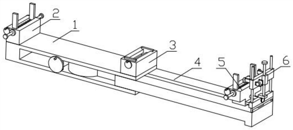
[0035] Combine below Figure 1-15 Illustrating this embodiment, a welding auxiliary device includes a welding side frame 1, a pipe fitting support frame 2, a welding table 3, an angle adjustment mechanism 4, a pipe fitting adjustment mechanism 5 and a welding gap adjustment mechanism 6. The pipe fitting support frame 2 It is fixedly installed on the welding side frame 1, the angle adjustment mechanism 4 is rotatably installed in the groove on the welding side frame 1, the welding table 3 is fixedly installed on the welding side frame 1, and the pipe fitting adjustment mechanism 5 is screwed with the angle adjustment mechanism 4. The pipe fitting adjusting mechanism 5 is slidably mounted on the angle adjusting mechanism 4 , and the welding gap adjusting mechanism 6 is fixedly mounted on the pipe fitting adjusting mechanism 5 .

specific Embodiment approach 2

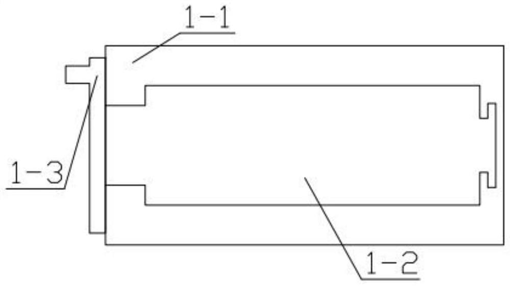
[0036] Combine below Figure 1-15 This embodiment will be described. This embodiment will further describe the first embodiment. The welding side frame 1 includes a U-shaped base 1-1, a worm 1-2, and a worm rotating disk 1-3. The worm 1-2 is rotatably installed on the U-shaped base 1-1. The worm 1-2 is fixedly connected with the worm rotating disc 1-3 in the groove set on the base 1-1.

specific Embodiment approach 3

[0037] Combine below Figure 1-15 This embodiment will be described, and the second embodiment will be further described in this embodiment. The pipe fitting support frame 2 includes a fixing table 2-1, a rotating gear 1 2-2, a limit gear ring 1 2-3, and a push threaded rod. One 2-4, limit plate one 2-5, spring one 2-6, connecting rod one 2-7, the fixing table 2-1 is fixedly installed on the U-shaped base 1-1, the connecting rod one 2-7 is rotated and installed In the grooves set on the fixing table 2-1, the two ends of the connecting rod 1 2-7 are respectively fixed with a rotating gear 1 2-2, a rotating gear 1 2-2 and a limit gear ring 1 2-3 The limit gear ring 1 2-3 is rotatably installed in the groove set on the fixing table 2-1, the limit gear ring 1 2-3 is threadedly connected with the push threaded rod 1 2-4, and the push threaded rod 1 2 -4 Passing through the fixed table 2-1 and fixedly connected with the limit plate 1 2-5, the limit plate 1 2-5 is slidably installed...


PUM


Abstract

The invention relates to a welding related device, more particularly to an auxiliary device for welding, comprising a welding side frame, a pipe fitting support frame, a welding table, an angle adjustment mechanism, a pipe fitting adjustment mechanism and a welding gap adjustment mechanism. The pipe fitting support frame It is fixedly installed on the welding side frame, and the angle adjustment mechanism is rotatably installed in the groove on the welding side frame. The welding table is fixedly installed on the welding side frame. On the adjustment mechanism, the welding gap adjustment mechanism is fixedly installed on the pipe fitting adjustment mechanism; the device can meet the two welding methods of butt joint and fillet joint, and the device can stably control the welding seam width to ensure the accuracy of the welding seam width.

Description

technical field [0001] The present invention relates to a welding related device, more particularly, to an auxiliary device for welding. Background technique [0002] Welding of pipe fittings is divided into butt joint and fillet joint. In the process of metal welding, if the weld is too wide and the size of the weld leg is too large, not only the welded joint is severely heated, the grain size of the weld is coarse, the plasticity and toughness are reduced, and the welding heat-affected zone is relatively large. It is easy to produce welding stress and deformation; in addition, waste materials increase the cost. On the contrary, if the weld seam is too narrow and the size of the weld leg is too small, the base metal and the weld seam may be poorly fused, causing stress concentration. Therefore, the correct determination of the weld size is the key to ensuring the welding quality. SUMMARY OF THE INVENTION [0003] The main technical problem to be solved by the present in...

Claims


Application Information

Patent Timeline
Patent Type & Authority Patents(China)
IPC IPC(8): B23K37/053B23K101/06
CPCB23K37/053B23K2101/06
Inventor 胡广荣
Owner 广东华焊智能设备科技有限公司
Why Eureka
Try Eureka