Efficient energy-saving injection mold

An injection mold, energy-saving technology, applied in the field of high-efficiency and energy-saving injection molds, can solve problems such as low work efficiency

Pending Publication Date: 2021-05-25
傅剑雄
View PDF5 Cites 0 Cited by
  • Summary
  • Abstract
  • Description
  • Claims
  • Application Information

AI Technical Summary

Problems solved by technology

[0003] At present, the existing injection mold processing process is generally intermittent production, such as injecting molten material after the mold is closed, the feeding mechanism needs to stop injecting the material after injecting the material, and wait for the material injected into the cavity to cool and form and take out the mold before proceeding to the next one. The injection step of each injection molding production process requires the use of cooling water to speed up the cooling and molding efficiency of plastic parts, but after each mold closing, wait for the material to be injected to complete the water cooling to speed up the molding efficiency, so the production of injection molds is subject to other constraints Due to the impact of intermittent processing methods such as mold closing, injection, cooling molding, mold opening, and material retrieving, the work efficiency is low. Therefore, we provide a high-efficiency and energy-saving system that can meet the dual-station alternate injection molding production based on the servo of the same feeding mechanism. type injection mold

Method used


Image

  • Efficient energy-saving injection mold
  • Efficient energy-saving injection mold
  • Efficient energy-saving injection mold

Examples


Embodiment Construction

[0027] The following will clearly and completely describe the technical solutions in the embodiments of the present invention with reference to the accompanying drawings in the embodiments of the present invention. Obviously, the described embodiments are only some, not all, embodiments of the present invention. Based on the embodiments of the present invention, all other embodiments obtained by persons of ordinary skill in the art without making creative efforts belong to the protection scope of the present invention.

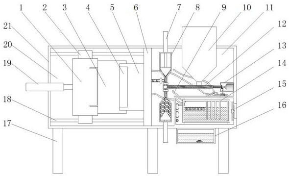
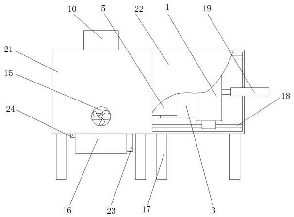
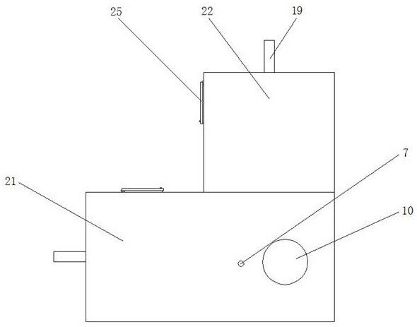
[0028] see Figure 1-11 , an embodiment provided by the present invention: a high-efficiency energy-saving injection mold, including a material tank 10 and a housing 21, the material tank 10 is arranged at one end of the top of the housing 21, and the bottom end of the material tank 10 extends to the housing 21, at the middle height position inside the material tank 10, the material is thermally melted inside the material tank 10, and the inside of the shell 2...


PUM


Abstract

The invention discloses an efficient energy-saving injection mold. The efficient energy-saving type injection mold comprises a material tank and a shell, the material tank is arranged at one end of the top of the shell, the bottom end of the material tank extends to the middle height position in the shell, and a partition plate is vertically welded to the position, on one side of the material tank, in the shell. A feeding chamber is formed in the side, close to the material tank, of the partition plate in the shell, and an injection molding chamber is formed in the side, away from the feeding chamber, of the partition plate in the shell. According to the efficient energy-saving injection mold, a pair of piston cylinders for containing molten materials in a reciprocating manner is symmetrically connected to a main material conveying pipe, and a set of fixed mold and movable mold for injection molding are arranged in the shell and a connecting box, so that the fixed mold and the movable mold at the shell and the connecting box can be used for alternately and intermittently machining and producing plastic parts; and the main material conveying pipe can continuously convey the materials, continuous feeding of the main conveying pipe cannot block a pipeline, the injection molding efficiency is improved, the volume of the materials needing to be injected in each time of injection molding production is easier to control, and the product quality is higher.

Description

technical field [0001] The invention relates to the technical field of injection molds, in particular to a high-efficiency and energy-saving injection mold. Background technique [0002] Injection molding is a method of stirring completely molten plastic materials through a screw at a certain temperature, injecting them into a mold cavity with high pressure, and obtaining molded products after cooling and solidification. This method is suitable for mass production of complex-shaped parts and is an important processing One of the methods, most of the plastic products are produced by a single injection mold. For many companies, the injection mold is an important equipment necessary for them to produce various plastic products. The products produced by the injection mold It has the advantages of light weight, high strength, good toughness, corrosion resistance, good insulation, easy coloring, easy molding, and low cost. Therefore, it has been widely used and loved and favored b...

Claims


Application Information

Patent Timeline
IPC IPC(8): B29C45/73B29C45/26B29C45/47
CPCB29C45/7312B29C45/2602B29C45/47Y02P70/10
Inventor 傅剑雄
Owner 傅剑雄
Why Eureka
Try Eureka