Three-dimensional vector soil pressure sensor capable of dynamically orienting

An earth pressure sensor, three-dimensional vector technology, applied in the direction of instruments, measuring devices, force/torque/power measuring instruments, etc., can solve problems such as different areas, shear damage, and complicated routing of stress measuring balls

Pending Publication Date: 2021-05-25
INST OF DEFENSE ENG ACADEMY OF MILITARY SCI PLA CHINA
View PDF0 Cites 0 Cited by
  • Summary
  • Abstract
  • Description
  • Claims
  • Application Information

AI Technical Summary

Problems solved by technology

[0004] In actual engineering, the accurate measurement of the three-dimensional stress state at a certain point has always been a difficult point in the engineering field. The existing test devices have the following problems: the geometric shape of the device is irregular, the area of ​​each surface is different, and the angle between the surfaces It is also different, which will lead to stress concentration and uneven stress distribution of the soil, reduce the accuracy of the stress test, and even induce shear failure of the soil along the plane of the device surface
In addition, the routing of the stress measurement ball composed of multiple earth pressure cells is complicated, and the line is outside the measurement surface of the earth pressure cell, which affects the propagation law of earth pressure and leads to a decrease in measurement accuracy
In addition, the existing schemes can only measure the size of the three-dimensional stress state, but ignore the description of each stress direction, resulting in the direction of the measured stress being unclear, and it is impossible to compare the measured stress state with the actual orientation of the project. Angles are associated, and the stress state cannot be described in engineering in the form of vector or tensor, so it is difficult to really describe the actual stress state of the project

Method used


Image

  • Three-dimensional vector soil pressure sensor capable of dynamically orienting
  • Three-dimensional vector soil pressure sensor capable of dynamically orienting
  • Three-dimensional vector soil pressure sensor capable of dynamically orienting

Examples


Embodiment Construction

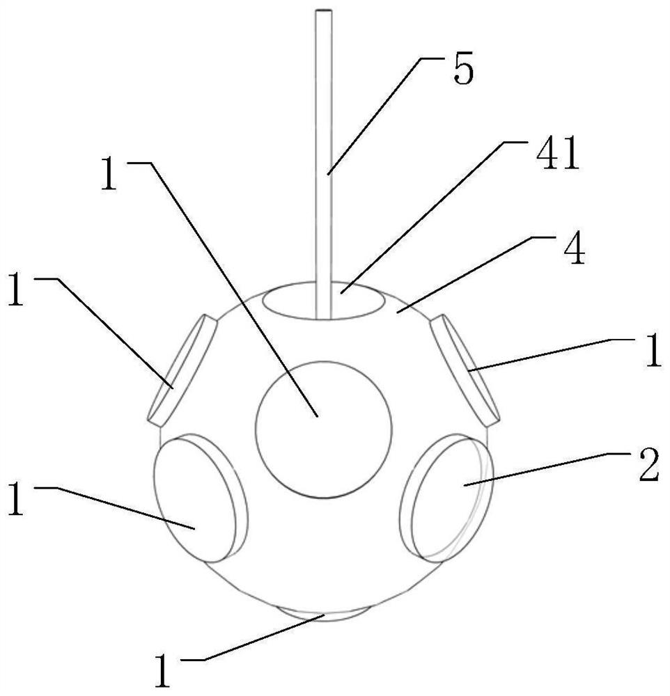
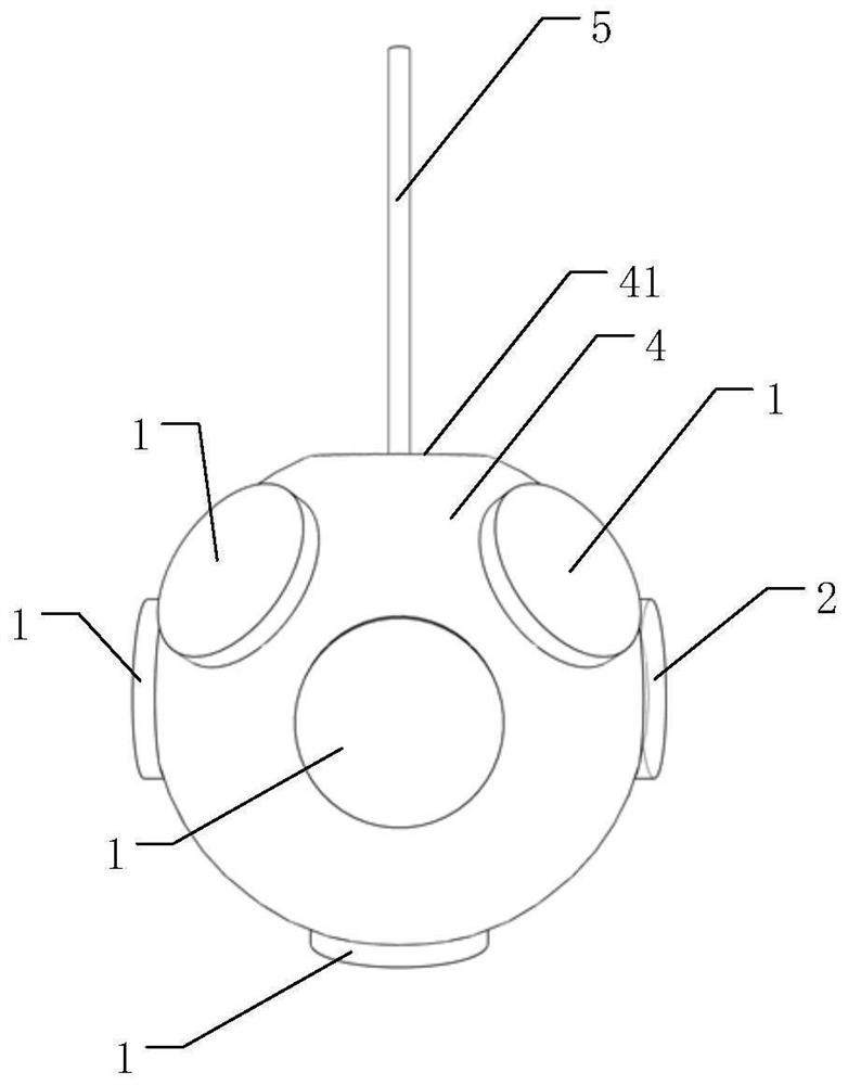
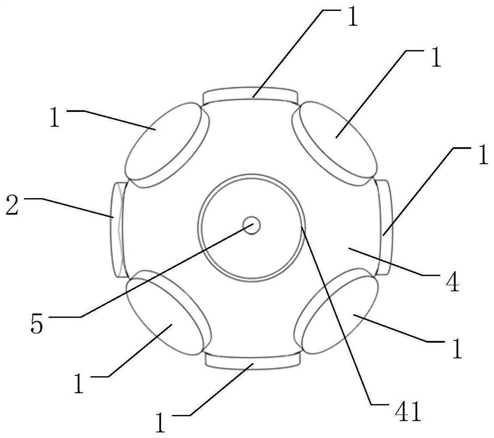
[0030] Embodiments of the present invention are described below through specific examples, and those skilled in the art can easily understand other advantages and effects of the present invention from the content disclosed in this specification. The present invention can also be implemented or applied through other different specific implementation modes, and various modifications or changes can be made to the details in this specification based on different viewpoints and applications without departing from the spirit of the present invention. It should be noted that the diagrams provided in the following embodiments are only schematically illustrating the basic concept of the present invention, and the following embodiments and the features in the embodiments can be combined with each other in the case of no conflict.

[0031] Wherein, the accompanying drawings are for illustrative purposes only, and represent only schematic diagrams, rather than physical drawings, and should...


PUM


Abstract

The invention belongs to the field of stress testing, and relates to a three-dimensional vector soil pressure sensor capable of dynamically orienting, which comprises a spherical base, a plurality of pressure modules arranged on the spherical base, a data acquisition module arranged in the spherical base and an optical fiber, the optical fiber is connected with the data acquisition module, the data acquisition module is connected with a plurality of wires, each pressure module is connected with one wire, the spherical base is further provided with a three-axis tilt angle sensor, and the three-axis tilt angle sensor is connected to the data acquisition module through one wire. On the basis of a spherical structure, dynamic monitoring of the stress direction can be achieved through the three-axis tilt angle sensor at low cost, real-time vectorization description of the three-dimensional stress state at one point in a soil body is truly achieved, and association with a project is achieved.

Description

technical field [0001] The invention belongs to the field of stress testing and relates to a dynamic orientable three-dimensional vector earth pressure sensor. Background technique [0002] In geotechnical engineering, affected by complex external loads and actual engineering environment, the stress state of soil is extremely complex. However, as a porous multiphase medium, the mechanical properties of soil are significantly affected by factors such as stress magnitude, stress direction, stress path, and stress history. In order to describe the stress state of the soil, the stress at a point is usually expressed as a vector. In three-dimensional space, the vector contains six degrees of freedom, so six independent variables are required to describe the stress state of a point. In the principal stress space, these six degrees of freedom reflect the three magnitudes of the principal stress and the three directions of the principal stress coordinate system. Therefore, only b...

Claims


Application Information

Patent Timeline
IPC IPC(8): G01L5/162
CPCG01L5/162
Inventor 董彤魏丽娟刘引陈晓张雪研
Owner INST OF DEFENSE ENG ACADEMY OF MILITARY SCI PLA CHINA
Why Eureka
Try Eureka