
Cooling electronic devices in a data center

A technology for data centers and electronic equipment, applied in data centers, electrical equipment components, electrical digital data processing, etc., can solve problems such as insufficient cooling, insufficient, high cost, etc., and achieve good performance results

Pending Publication Date: 2021-05-25
GOOGLE LLC
View PDF0 Cites 0 Cited by
  • Summary
  • Abstract
  • Description
  • Claims
  • Application Information

AI Technical Summary

Problems solved by technology

[0004] A consequence of inadequate and / or insufficient cooling may be that one or more electronic devices on the tray fail due to the temperature of the device exceeding the maximum rated temperature
While some redundancy can be built into computer data centers, server racks, or even individual trays, failure of equipment due to overheating can be very costly in speed, efficiency, and expense

Method used


Image

  • Cooling electronic devices in a data center
  • Cooling electronic devices in a data center
  • Cooling electronic devices in a data center

Examples


Embodiment Construction

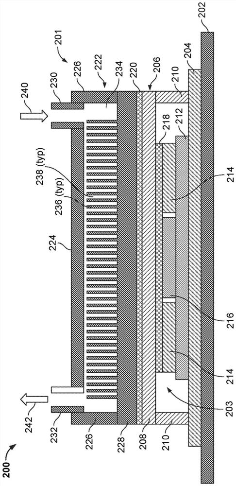
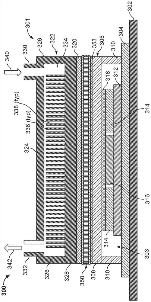
[0048] In some example embodiments, a cooling system for rack-mounted electronic equipment (eg, servers, processors, storage, networking equipment, etc.), such as in a data center, is disclosed. In various disclosed embodiments, the cooling system may be or include a liquid cooling plate assembly that is part of or integrated with the server tray enclosure. In some embodiments, a liquid cooling plate assembly includes a base and a top that in combination form a cooling fluid flow path and a thermal interface between one or more heat generating devices and the cooling fluid through which cooling fluid is circulated .

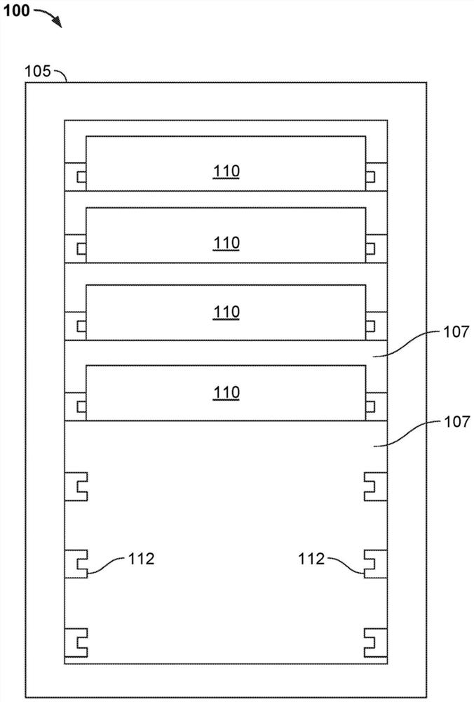
[0049] figure 1 An example system 100 is shown that includes a server rack 105 (eg, a 13-inch or 19-inch server rack) and a plurality of server rack subassemblies 110 mounted within the rack 105 . While a single server rack 105 is shown, server rack 105 may be one of several server racks within system 100, which may include a server farm or contain various rack...


PUM


Abstract

A cooling system, for example, for rack mounted electronic devices (e.g., servers, processors, memory, networking devices or otherwise) in a data center. In various disclosed implementations, the cooling system may be or include a liquid cold plate assembly that is part of or integrated with a server tray package. In some implementations, the liquid cold plate assembly includes a base portion and a top portion that, in combination, form a cooling liquid flow path through which a cooling liquid is circulated and a thermal interface between one or more heat generating devices and the cooling liquid.

Description

technical field [0001] This document relates to systems and methods for providing cooling to electronic equipment, such as computer server racks and related equipment in computer data centers, using cold plates. Background technique [0002] Computer users are often concerned with the speed (eg, megahertz and gigahertz) of a computer's microprocessor. Many computer users forget that this speed often comes with higher power consumption. This power dissipation also generates heat. That's because, through the simple laws of physics, all that power has to go somewhere, where it ends up being converted to heat. A pair of microprocessors mounted on a single motherboard can draw hundreds of watts or more. Multiply that number by thousands (or tens of thousands) to account for the many computers in a large data center, and one can easily appreciate the heat that might be generated. The impact of the power consumed by a critical load in a data center is often compounded when all ...

Claims


Application Information

Patent Timeline
Patent Type & Authority Applications(China)
IPC IPC(8): H05K7/20
CPCH05K7/20772G06F1/20G06F2200/201H05K7/1487H05K7/1489H05K7/20254H05K7/20409H05K7/20763
Inventor 马达胡苏丹·克里希南·伊扬格格雷戈里·西齐科夫李元乔治·派迪拉昆文秀康泰久
Owner GOOGLE LLC
Learn More