Capacity ventilation control method and system of turbine respirator

A control method and control system technology, applied in the field of ventilators, can solve problems such as cumbersome air circuit structure, achieve accurate and reliable effects, improve ventilation performance and control precision, and simplify the air circuit structure

Pending Publication Date: 2021-05-28
河北谊安奥美医疗设备有限公司
View PDF7 Cites 4 Cited by
  • Summary
  • Abstract
  • Description
  • Claims
  • Application Information

AI Technical Summary

Problems solved by technology

This method requires the cooperation of the turbine and the proportional valve to adjust the ventilation, and the gas circuit structure is relatively cumbersome, so technical improvement is required

Method used


Image

  • Capacity ventilation control method and system of turbine respirator
  • Capacity ventilation control method and system of turbine respirator

Examples


Embodiment 1

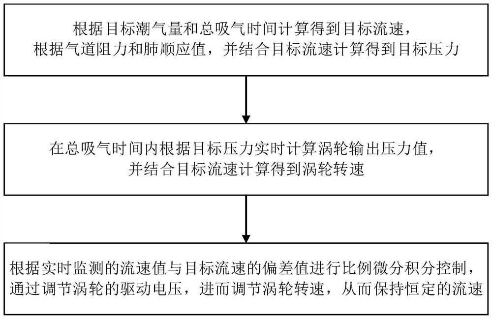
[0047] Such as figure 1 As shown, Embodiment 1 of the present invention proposes a volume ventilation control method of a turbo ventilator, and the specific steps are as follows:

[0048] Step 1) is the stage of calculating the tidal volume target flow rate and target pressure. First calculate the target flow rate based on tidal volume and inspiratory time:

[0049] Qt = SetVt / Tinsp;

[0050] Among them, Qt is the target flow rate, SetVt is the target tidal volume, and Tinsp is the inspiratory time.

[0051] Calculate target pressure from air resistance and compliance values:

[0052] Pt=R*Qt+SetVt / C;

[0053] Among them, Pt is the target pressure, R is the airway resistance, and C is the lung compliance.

[0054] Step 2) Calculate the turbine output pressure value at each moment in real time according to the target pressure during the inhalation process:

[0055] Pi=VentT / Tinsp*Pt;

[0056] Among them, VentT is the running inspiratory time, and Tinsp is the total inspi...

Embodiment 2

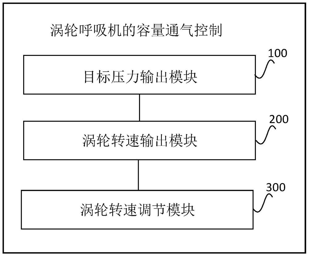
[0063] Such as figure 2 As shown, Embodiment 2 of the present invention proposes a volume ventilation control system for a turbo ventilator. The system includes: a target pressure output module 100, a turbine speed output module 200, and a turbine speed adjustment module 300; the specific implementation method is the same as that in Embodiment 1. in,

[0064] The target pressure output module 100 is used to calculate the target flow rate according to the target tidal volume and the total inspiratory time, and calculate the target pressure according to the airway resistance and lung compliance value combined with the target flow rate;

[0065] The turbine speed output module 200 is used to calculate the turbine output pressure value in real time according to the target pressure during the total intake time, and calculate the turbine speed in combination with the target flow rate;

[0066] The turbine speed adjustment module 300 is used to perform proportional differential in...


PUM


Abstract

The invention discloses a volumetric ventilation control method and system for a turbo ventilator, and the method comprises the steps: 1) calculating a target flow velocity according to a target tidal volume and total inspiration time, and calculating a target pressure according to airway resistance and a lung compliance value in combination with the target flow velocity; 2) calculating a turbine output pressure value in real time according to the target pressure within the total air suction time, and conducting calculating to obtain a turbine rotating speed in combination with the target flow speed; and (3) conducting proportional differential integral control according to the deviation value of the flow velocity value monitored in real time and the target flow velocity, adjusting the rotating speed of the turbine by adjusting the driving voltage of the turbine, and thereby keeping the constant flow velocity. According to the ventilation control method, a method in the prior art that a proportional valve is needed for adjusting the flow speed is effectively improved, the gas circuit structure is simplified, the ventilation performance and control precision of the turbine are improved, the turbine controls the ventilation effect accurately and reliably through actual ventilation use on the breathing machine, and the good effect is achieved.

Description

technical field [0001] The invention relates to the technical field of ventilators, in particular to a volume ventilation control method and system for a turbo ventilator. Background technique [0002] Turbine ventilator is a commonly used equipment in hospitals. The turbine ventilator is an electric and electronically controlled driving method with a turbine as the driving air source. After the turbine is energized, it generates airflow at a certain rotational speed, and its rotational speed determines the airflow velocity and pressure. VCV (short for Volume controlled ventilation, that is, volume controlled ventilation) controlled ventilation requires real-time adjustment of the turbine speed to maintain a constant flow rate during the inhalation process to achieve the purpose of accurately controlling the target tidal volume. [0003] At present, the method of the turbine ventilator is to provide a certain rotational speed by the turbine, and then adjust the flow rate out...

Claims


Application Information

Patent Timeline
Patent Type & Authority Applications(China)
IPC IPC(8): A61M16/00
CPCA61M16/00A61M16/0003A61M2016/003A61M2205/07A61M2205/3334A61M2205/33
Inventor 华威解立新刘加龙
Owner 河北谊安奥美医疗设备有限公司
Why Eureka
Try Eureka