
Hydrogen production device

A technology for a hydrogen production device and a hydrogen generator, which is applied in the fields of hydrogen, hydrogen/syngas production, inorganic chemistry, etc., can solve the problems of low hydrogen production efficiency, large consumption of combustion catalysts, and single heating method, and achieve overall sealing performance. Good, various heating methods, high heat utilization effect

Pending Publication Date: 2021-05-28
SICHUAN WOYOUDA TECH GRP CO LTD
View PDF8 Cites 2 Cited by
  • Summary
  • Abstract
  • Description
  • Claims
  • Application Information

AI Technical Summary

Problems solved by technology

[0003] In the existing hydrogen production process, the method of hydrogen production using the raw material liquid of methanol and water requires a high-temperature device in the equipment. At present, in the existing hydrogen production device, the combustion catalyst is placed outside the combustion catalytic tube, and the combustion catalytic reaction In the process, the combustion catalyst consumes a lot, and the replacement of the combustion catalyst is inconvenient, and the heat utilization rate is not high. The heating method is relatively simple, and the temperature required for the hydrogen production process cannot be guaranteed and controlled, and the hydrogen production efficiency is low.

Method used


Image

  • Hydrogen production device
  • Hydrogen production device
  • Hydrogen production device

Examples


Embodiment 1

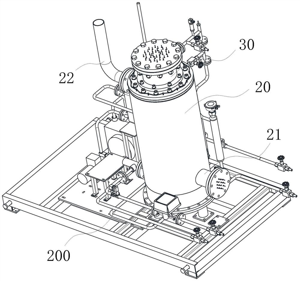
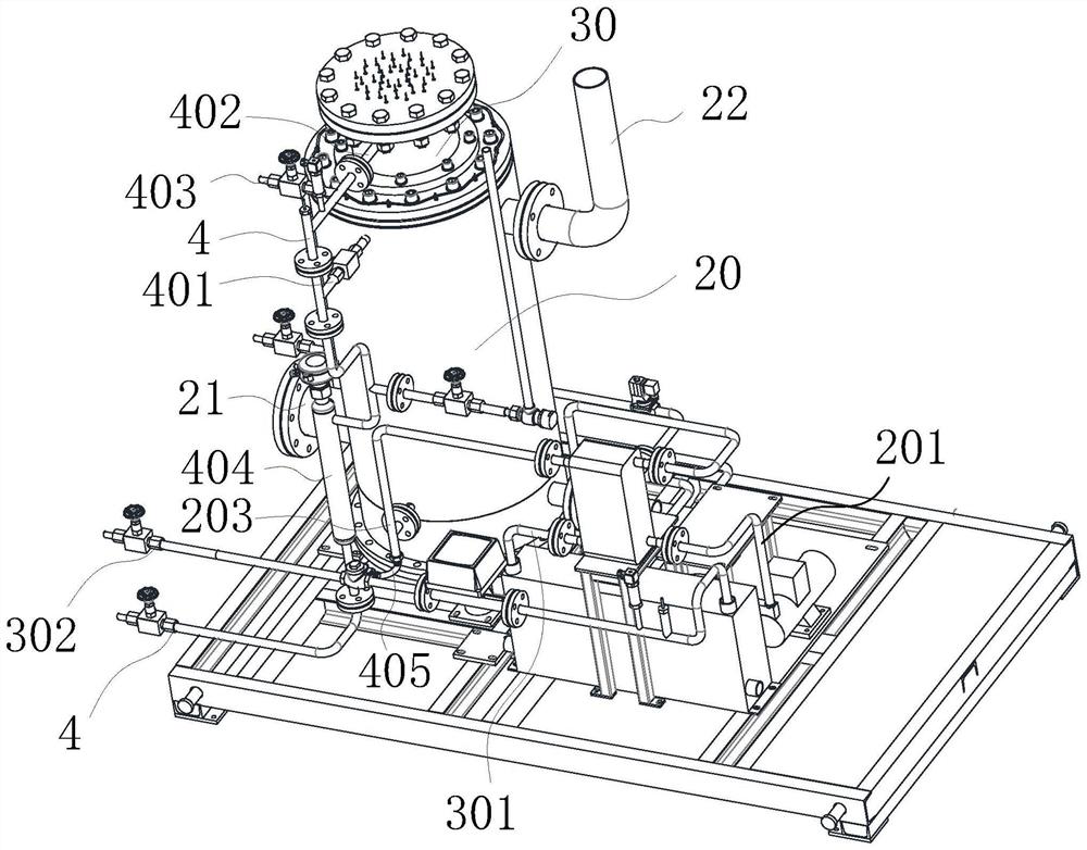
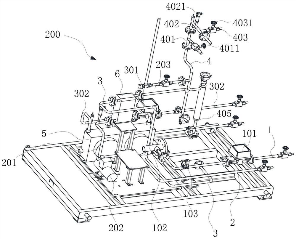
[0061] see Figure 5 , Figure 6 and Figure 7 , a hydrogen production device, comprising: a steam generator 20 for generating steam required for hydrogen production and a hydrogen generator 30 for generating hydrogen by reacting with the steam.

[0062] Specifically, the steam generator 20 includes an outer cylinder 23 and an inner cylinder 24 sleeved in the outer cylinder 23. The inner and outer cylinders 23 are both heat-insulating shells. Cavity 60, the side of the outer cylinder 23 is provided with an electric heating port communicating with the heating chamber 50; the heating chamber 50 has built-in a plurality of combustion catalyst tubes 51 communicating with the external exhaust gas; , the steam pipe 62 is used to transport the steam generated in the steam generator 20; the overheating chamber 60 communicates with one end of the combustion catalyst pipe 51; The hydrogen production catalyst reacts to generate hydrogen; wherein, a combustion catalyst is arranged in t...

Embodiment 2

[0071] This embodiment is a further optimization scheme on the basis of embodiment 1:

[0072] Such as Figure 14 As shown, fins 53 are distributed on the surface of the combustion catalyst tube 51 to increase the heat dissipation area, improve the transfer of heat generated by the combustion catalyst tube 51 to the liquid, and accelerate the evaporation of the liquid.

[0073] Further, a porous partition 52 is arranged in the combustion catalyst tube 51 to form an accommodating space, so that the combustion catalyst is placed in the combustion catalyst tube 51, and the porous partition 52 is distributed with air holes smaller than the diameter of the combustion catalyst, which is convenient for entering the combustion catalyst tube 51. The exhaust gas inside reacts with the combustion catalyst. Of course, one or more porous partitions 52 in the combustion catalyst tube 51 can be provided and distributed in the combustion catalyst tube 51 at intervals. The porous partition 52...

Embodiment 3

[0075] This embodiment can be combined with Implementation 1-2 separately or simultaneously, as a further improvement:

[0076] Such as Figure 12 As shown, the steam generator 20 also includes a base 40 with an exhaust gas inlet cavity 42 inside, and at least one exhaust gas inlet 41 is provided on one side of the exhaust gas inlet cavity 42 for communicating with the external exhaust gas; see Figure 7 and Figure 11 , the overheating chamber 60 , the heating chamber 50 and the exhaust gas inlet chamber 42 are stacked in sequence in the vertical direction, and a partition 25 is arranged between them. A partition 25 is arranged between the overheating chamber 60 , the heating chamber 50 , and the exhaust gas intake chamber 42 that are successively stacked in the vertical direction, so that a relative buffer area is formed between each layer, for example, a partition is arranged in the exhaust gas intake chamber 42 25. When the exhaust gas enters the exhaust gas intake cavit...


PUM

PropertyMeasurementUnit
densityaaaaaaaaaa

Abstract

The invention discloses a hydrogen production device. The hydrogen production device comprises a steam generator which is used for generating steam required by hydrogen production and comprises a heating cavity, and a plurality of combustion catalyst pipes communicated with external tail gas are arranged in the heating cavity. The hydrogen production device further comprises an overheating cavity and a hydrogen producer. The overheating cavity is internally provided with a steam pipe communicated with the heating cavity, and the steam pipe is used for conveying steam generated in the steam generator. The overheating cavity is communicated with one ends of the combustion catalyst pipes. The hydrogen producer is connected with the steam pipe, and steam input by the steam pipe reacts with a hydrogen production catalyst in the hydrogen producer to generate hydrogen. A combustion catalyst is arranged in the combustion catalyst pipes, and liquid is stored outside the combustion catalyst pipes. The hydrogen production device has the advantages that the heat utilization rate is high, the heating modes are diversified, the temperature needed in the hydrogen production process can be adjusted in real time, and the hydrogen production efficiency is high.

Description

technical field [0001] The invention relates to the technical field of chemical equipment, in particular to a hydrogen production device. Background technique [0002] Hydrogen is the gas with the smallest density known in the world and the substance with the smallest relative molecular mass. Hydrogen is the most abundant element in the universe. The mass of hydrogen is only 1 / 14 of that of air, that is, at 0°C, under a standard atmospheric pressure, The density of hydrogen is 0.0899g / L. A large number of biological studies have shown that hydrogen has the effect of selectively neutralizing free radicals and nitrite anions, which is the basis for hydrogen to fight oxidative damage and treat diseases. Studies have shown that there are many types of diseases that hydrogen can treat. [0003] In the existing hydrogen production process, the method of hydrogen production using the raw material liquid of methanol and water requires a high-temperature device in the equipment. At...

Claims


Application Information

Patent Timeline
Patent Type & Authority Applications(China)
IPC IPC(8): C01B3/32
CPCC01B3/323C01B2203/0811C01B2203/1223Y02E60/36Y02E70/30
Inventor 张会强
Owner SICHUAN WOYOUDA TECH GRP CO LTD
Learn More