Steel box girder bridge deck slab structure and paving method

A technology for steel box girders and bridge decks, applied in bridges, bridge parts, bridge construction, etc., can solve problems that affect construction efficiency, affect the construction quality of bridge deck concrete cushions, and damage studs

Pending Publication Date: 2021-05-28
上海瑞史坦环保科技有限公司
View PDF0 Cites 0 Cited by
  • Summary
  • Abstract
  • Description
  • Claims
  • Application Information

AI Technical Summary

Problems solved by technology

Due to the existence of steel studs, it is difficult to use large-scale machinery to complete the removal of the original bridge deck concrete, which greatly affects the construction efficiency, and even

Method used


Image

  • Steel box girder bridge deck slab structure and paving method
  • Steel box girder bridge deck slab structure and paving method
  • Steel box girder bridge deck slab structure and paving method

Examples


Embodiment 1

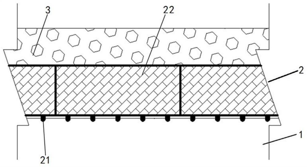
[0044] A steel box girder bridge deck structure, such as figure 1 As shown, it includes steel box girder 1, concrete module cushion 2 and asphalt layer 3 arranged in sequence from bottom to top. On the top plate of box girder 1.

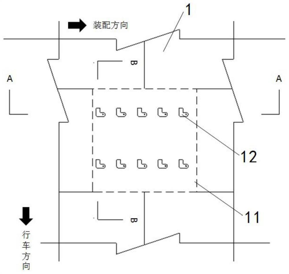
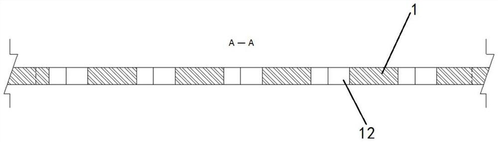
[0045] Specifically, such as Figure 2-6 As shown, a rectangular assembly area 11 is provided on the top plate of the steel box girder 1. The shape and size of the assembly area 11 match the concrete module 22. Two rows of assembly holes 12 are arranged in parallel in the assembly area 11, and the assembly holes 12 are horizontal The direction section is L-shaped, one side is parallel to the transverse section of the bridge deck, that is, the assembly direction, and the other side is parallel to the longitudinal section of the bridge deck, that is, the driving direction, and the end of the side parallel to the assembly direction is hemispherical, which can make the fixed The bolt and the assembly hole better form a hoop effect.

[0046] like Fig...


PUM


Abstract

The invention relates to a steel box girder bridge deck slab structure and a paving method. The steel box girder bridge deck slab structure comprises a steel box girder (1), a concrete module cushion layer (2) and an asphalt layer (3) which are sequentially arranged from bottom to top, wherein the concrete module cushion layer (2) is clamped on the steel box girder (1). Compared with the prior art, the steel box girder bridge deck slab structure can ensure road quality of the steel box girder bridge and can also improve the maintainability of the road.

Description

technical field [0001] The invention relates to the technical field of bridge engineering, in particular to a steel box girder bridge deck structure and a paving method. Background technique [0002] Steel box girder is also called steel plate box girder, because it looks like a box, so it is called steel box girder. The steel box girder deck has the advantages of light weight, large spanning capacity, simple construction, and significant economy. It is especially suitable for long-span bridges and has been widely used at home and abroad. [0003] The traditional steel box girder bridge deck pavement is usually realized in the following way: welding studs on the steel box girder, then pouring a concrete integral cushion, and then paving asphalt on the concrete cushion, and finally forming a bridge that can meet the needs of vehicles. The required bridge deck road structure system. The purpose of welding studs on the steel box girder is mainly to solve the bonding problem b...

Claims


Application Information

Patent Timeline
IPC IPC(8): E01D19/12E01D2/04E01D21/00
CPCE01D2/04E01D19/125E01D21/00
Inventor 袁侠斌
Owner 上海瑞史坦环保科技有限公司
Why Eureka
Try Eureka