Eureka AIR delivers breakthrough ideas for toughest innovation challenges, trusted by R&D personnel around the world.

LED long-afterglow composite light-emitting strip-shaped lens and light-emitting device comprising LED long-afterglow composite light-emitting strip-shaped lens structure

A technology of long afterglow luminescence and long afterglow luminous powder, which is applied to optical elements for changing the spectral characteristics of emitted light, semiconductor devices of light-emitting elements, light sources, etc. Problems such as poor directivity, to achieve the effect of reducing light energy waste, reducing matching errors, and reducing errors

Pending Publication Date: 2021-05-28
方显峰
View PDF6 Cites 0 Cited by
  • Summary
  • Abstract
  • Description
  • Claims
  • Application Information

AI Technical Summary

Problems solved by technology

[0007] As mentioned above, the long afterglow photoelectric products in the prior art, the long afterglow material combined with the LED basically adopts a planar covering arrangement, and is mainly formed by liquid pouring and leveling, mainly in a layered form, and the long afterglow material is provided below or inside. LED, LED, only SMD type (SMD) LED has a better luminous effect, and the luminous effect of LEDs in other packaging methods is not ideal, and some products also have a light-transmitting protective panel above the long-lasting light-emitting layer; especially long-lasting materials The luminous effect of the setting method in contact with the LED is the main one. When the LED emits light, part of the light energy excites the long afterglow, and part of the unconverted light energy diffuses and emits light after passing through the long afterglow light-emitting layer. Therefore, the prior art products must have the following defects:
[0008] 1. The long afterglow light-emitting layer is mainly excited by transmission. At present, LEDs mainly include SMD type (chip type), COB type (integrated type), LAMP type (in-line type) or imitation lumen lamp beads. The packaging method and product shape , size specifications, luminous performance, welding methods are different, and the focus of use is also different. Some LEDs have their own primary packaging, especially the height (thickness) between the top of the LED luminous body and the circuit board layer. 1. Therefore, the thickness of the long afterglow luminescent layer on the top of the LED and on the sides of the LED is uneven. Generally, the thickness of the long afterglow luminescent layer on the top of the LED is smaller than the thickness of the long afterglow luminescent layer on the side of the LED, which is easy to cause the long afterglow luminescent layer above the LED. The thickness is too thin, resulting in insufficient afterglow brightness, or the thickness of the long afterglow luminescent layer around the LED side is too thick, resulting in insufficient excitation of the long afterglow luminescent layer, resulting in waste of light energy; and the long afterglow material of the existing LED long afterglow luminous body It is difficult to make various three-dimensional shapes, and the three-dimensional luminous effect is not good, so that the luminous viewing angle, especially the luminous viewing angle of the side light, is limited; in short, the utilization rate of LED light energy is low, and the luminous effect and LED light distribution and output effect are poor.
[0009] 2. Since the long afterglow luminescent layer is set above the LED luminous body, the LED light will be absorbed and scattered by the long afterglow powder when it exits the long afterglow layer, which will lead to excessive loss of light intensity and poor directivity of the LED exit light (the exit light loses directionality ), it is difficult to achieve output according to the design of the optical path [it is convenient to realize parameters such as luminous angle, beam angle or light intensity distribution, such as concentrating or diverging or polarized (the outgoing main beam exits at an acute angle with the luminous axis) or, polarized light (sometimes called side Light, the outgoing light energy distribution on one side is greater than the outgoing light energy distribution on the other side), etc.], especially for fixed-point (area) projection that requires lighting purposes or directional (angle) projection requirements that require indication purposes The luminous equipment cannot meet the requirements at all, and the existing products have a short luminous range and a short viewing distance, which is especially unfavorable for traffic, security, emergency and other purposes.
[0010] 3. The long afterglow luminescent layer covers the top of the LED luminous body, and the light emitted by the LED luminous body through the long afterglow luminescent material is a mixed-color luminescence with the excited light of the long afterglow, resulting in impure luminous color and shifted chromaticity, resulting in long afterglow Excessive influence and interference on the luminous spectrum of LED light-emitting devices such as chromaticity or color temperature when excited by light affects the luminous spectrum of the original LED: when white LEDs corresponding to lighting purposes are used as excitation light sources, the quality of the white light spectrum is seriously affected , when the excitation light source of other colors is used, it will affect the luminous chromaticity, resulting in limited application range
[0011] In short, the long-afterglow light-emitting products of the prior art have the above-mentioned fatal defects and other shortcomings, which restrict their development and become an urgent problem to be solved in the industry.

Method used


Image

  • LED long-afterglow composite light-emitting strip-shaped lens and light-emitting device comprising LED long-afterglow composite light-emitting strip-shaped lens structure
  • LED long-afterglow composite light-emitting strip-shaped lens and light-emitting device comprising LED long-afterglow composite light-emitting strip-shaped lens structure
  • LED long-afterglow composite light-emitting strip-shaped lens and light-emitting device comprising LED long-afterglow composite light-emitting strip-shaped lens structure

Examples


Embodiment 1

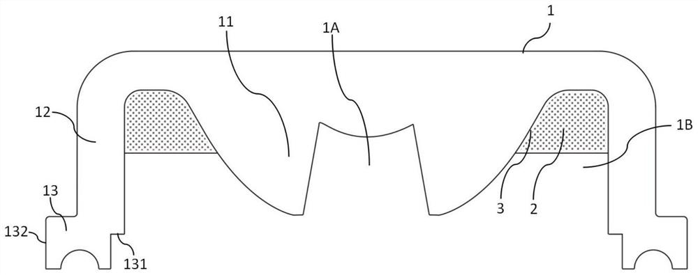
[0192] Embodiment 1 of the present invention proposes a LED long afterglow composite light-emitting strip lens with a light-gathering structure, such as Figure 22 As shown, it includes a lens body structure (110), the central optical main part of which is a bar-shaped structure whose cross-section gradually increases from bottom to top, and the center of the bottom of the central optical main part is provided with an accommodating groove for the light of the bar-shaped light source to enter (110A), the inner wall of the accommodation groove (110A) is a parabolic cylinder, and the two sides of the lens body structure (110) are provided with the optical body part (1110) connected with the middle light distribution, along the middle light distribution optical body part (1110) ) arranged in parallel, the downturned transparent surround acts as a side surround (1120), and an accommodation along the extending direction of the accommodation groove (110A) is provided between the middl...

Embodiment 2

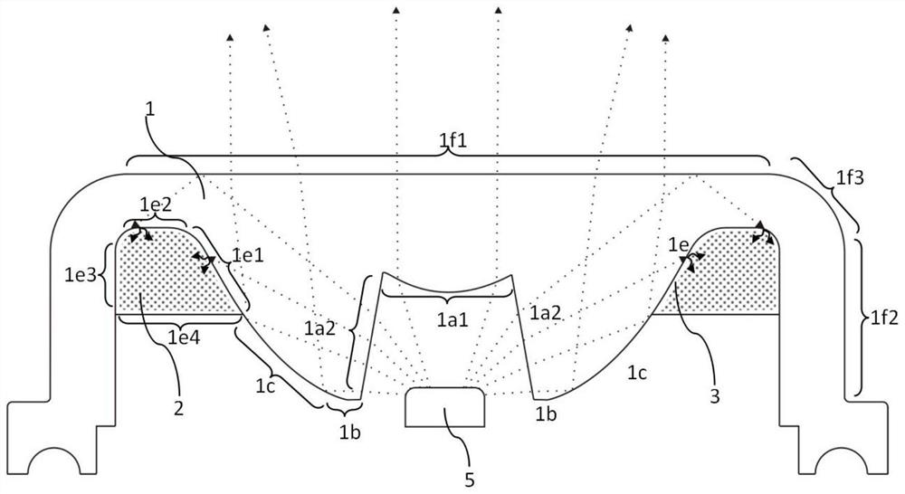
[0212] Embodiment 2 of the present invention provides a LED long afterglow composite light-emitting strip lens with a diverging structure, such as Figure 29 As shown, it includes a lens body structure (210), the edge of the lens body structure (210) has an upturned transparent surround as a side wall portion (2120), the central optical body portion (2110) has a raised arched section, and the central The center of the bottom of the optical body part (2110) is provided with an accommodating groove (210A) capable of entering light from a bar-shaped light source. The curvature of the light incident surface (210a1) is greater than the curvature of the corresponding part of the light exit surface (210f), and an accommodation parallel to the accommodation groove (210A) is provided between the middle light distribution optical main part (2110) and the side surrounding part (2120). In the groove (210B), the long-lasting luminescent molded body (220) is formed by pouring the liquid mix...

Embodiment 3

[0219] Embodiment 3 of the present invention provides an LED long afterglow composite light-emitting strip lens with a TIR total reflection structure combined with a prism directional angle exit structure, such as Figure 35As shown, it includes a strip-shaped lens body structure (310). The lens body structure (310) is a strip-shaped structure with a transparent surround, and its central optical main body gradually increases in size from bottom to top. The bottom center of the central optical main body An accommodating groove (310A) capable of entering light from a bar-shaped light source is provided, and an intermediate light distribution optical main body (3110) conjoined with the intermediate light distribution optical main body (3110) is provided on both sides of the lens body structure (310). ) arranged in parallel, the downturned transparent surround acts as a side surround (3120), and an accommodation along the extending direction of the accommodation groove (310A) is pr...


PUM

PropertyMeasurementUnit
particle diameteraaaaaaaaaa
thicknessaaaaaaaaaa
thicknessaaaaaaaaaa

Abstract

An LED long-afterglow composite light-emitting strip-shaped lens comprises a lens body structure (1) and a long-afterglow light-emitting forming body (2), the lens body structure (1) comprises a strip-shaped middle light distribution optical main body part (11) and side surrounding parts (12) which are arranged on the two sides of the middle light distribution optical main body part respectively and connected with the outer side parts of the middle light distribution optical main body part, and the middle portion of the bottom of the middle light distribution optical main body part (11) is concaved inwards to form a strip-shaped containing groove (1A); the lens body structure (1) is provided with accommodating grooves (1B) or fitting structures (1D) according to locations, the long-afterglow light-emitting forming body (2) is combined on the lens body structure (1) through the accommodating grooves (1B) or the fitting structures (1D), and the combining surface thereof is provided with a transparent light guide medium (3) to form a light guide coupling surface (1e), the lens can be combined with an LED to be manufactured into various light emitting devices; and the light-energy distribution proportion can be adjusted, light distribution is conducted on an emergent light field, the lens body structure achieves the light coupling effect with the long-afterglow light-emitting forming body (2), and at least part of emergent light of the LED light-emitting body can be emitted according to the light path design while the afterglow light emitting advantages are reserved.

Description

technical field [0001] The invention relates to the field of light-emitting optical devices and light-emitting equipment, in particular to an LED long-afterglow composite light-emitting strip lens and a light-emitting equipment containing the LED long-afterglow composite light-emitting strip lens structure. Background technique [0002] Long afterglow luminescent material is short for long afterglow material, also known as luminous material, which is a kind of photoluminescent material: under the excitation of light source, it emits visible light and stores part of the obtained light energy. After the excitation stops, it emits visible light in the form of light. The energy is released slowly, and its luminous brightness is related to the properties of the luminescent material itself, and also related to the thickness of the long-lasting luminescent layer and the concentration of the long-lasting luminescent powder; due to the continuous development and progress of LED combin...

Claims


Application Information

Patent Timeline
Patent Type & Authority Applications(China)
IPC IPC(8): F21V5/10F21V5/04F21V9/32F21V9/38F21Y115/10
CPCF21V5/04F21Y2115/10F21V5/10F21V9/32F21V9/38
Inventor 方显峰
Owner 方显峰
Why Eureka
Eureka Blog
Learn More