MEMS-based three-dimensional intelligent soil displacement monitoring device and method

A technology of soil displacement and monitoring devices, which is applied in the direction of measuring devices, electromagnetic measuring devices, and electrical devices, etc., which can solve the problems of inability to obtain the displacement of mutation points, inability to realize real-time monitoring and remote sensing, and great influence of temperature optical fibers. , to achieve the effect of avoiding laying optical cables and blocking traffic monitoring, real-time measurement of intelligence level, and simple embedding in soil

Pending Publication Date: 2021-05-28
GUILIN UNIV OF ELECTRONIC TECH
View PDF0 Cites 12 Cited by
  • Summary
  • Abstract
  • Description
  • Claims
  • Application Information

AI Technical Summary

Problems solved by technology

[0004] 1. BOTDR optical fiber sensing technology has high requirements for equipment and requires laying of optical fibers. In addition, temperature has a great influence on optical fibers, and a large number of simulation tests are required.
[0005] 2. TDR Time Domain Reflectometry Technology Only when it is deformed by shear force, tension or the combination of the two, the TDR cable will generate a cable signal, and the displacement of the mutation point cannot be obtained
[0006] 3. The resolution of GPR geological radar technology is greatly disturbed by electromagnetic waves around the site, the depth is limited, and real-time monitoring and remote sensing cannot be realized. When it is implemented in the road operation stage, traffic needs to be closed, and its long-term monitoring method has relatively large limitations

Method used


Image

  • MEMS-based three-dimensional intelligent soil displacement monitoring device and method
  • MEMS-based three-dimensional intelligent soil displacement monitoring device and method
  • MEMS-based three-dimensional intelligent soil displacement monitoring device and method

Examples


Embodiment

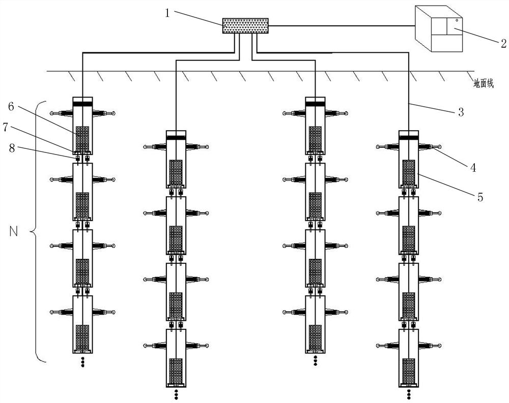
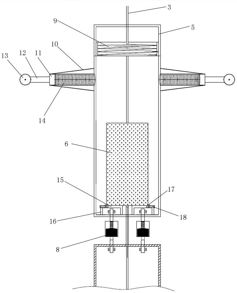
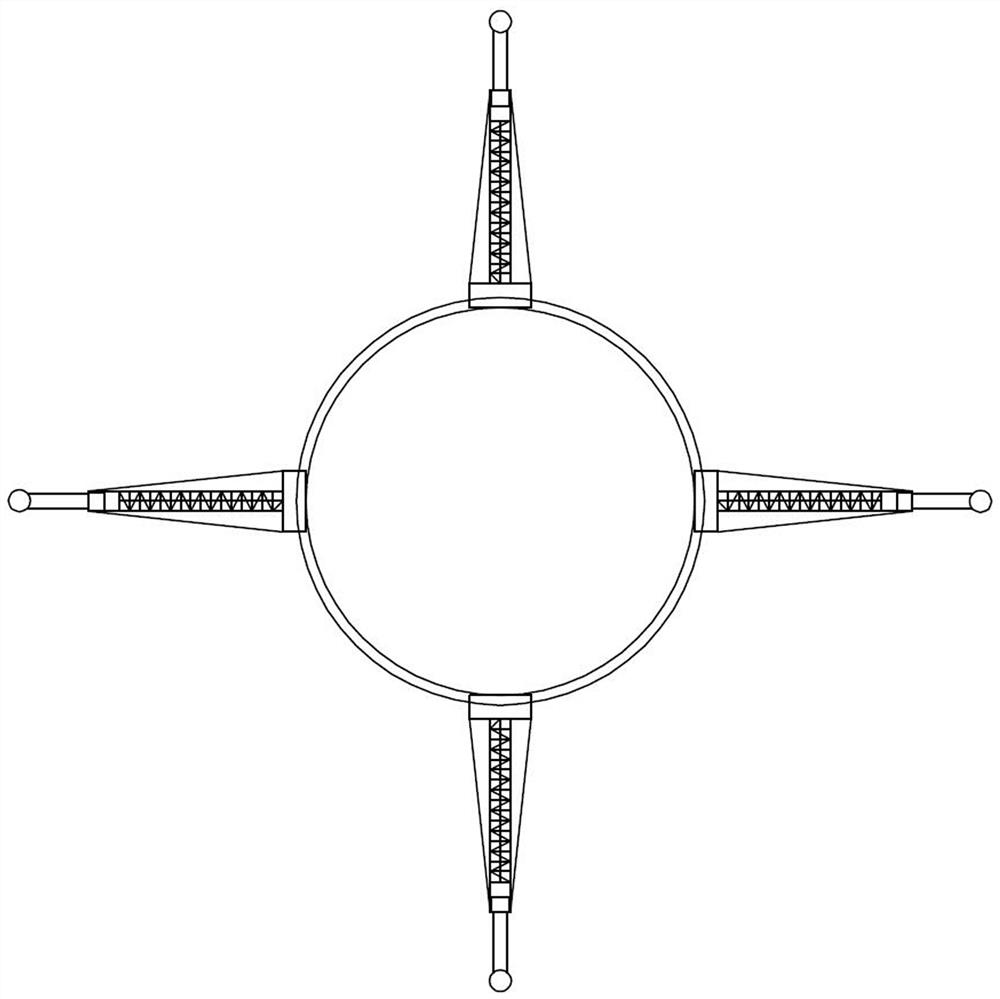
[0084] Such as figure 1 , figure 2 with image 3 Shown:

[0085] A MEMS-based three-dimensional intelligent soil displacement monitoring device, comprising a data acquisition server 2, an inclinometer tube vertically buried in the Quaternary overburden of a point to be monitored, and an N Level monitoring rods 5, fixed mounting brackets 7 fixedly installed at the inner lower end of each level of monitoring rods 5, MEMS attitude angle sensors 6 are anchored on the fixed mounting brackets, and each MEMS attitude angle sensors 6 are connected in series through multi-cascade connection lines 3, and the topmost The MEMS attitude angle sensor 6 is connected with the USB expander 1 through the multi-cascade connection line 3, and the USB expander 1 is connected with the data acquisition server 2 through the data line;

[0086] For the MEMS attitude angle sensor 6, each MEMS attitude angle sensor 6 is provided with a unique ID number, and the address of each ID number corresponds...


PUM


Abstract

The invention discloses a MEMS-based three-dimensional intelligent soil displacement monitoring device and method, and the device comprises a data collection server, an inclinometer tube, N stages of monitoring rods disposed in the inclinometer tube, and MEMS attitude angle sensors anchored at the lower ends of the interiors of each stage of monitoring rods through fixed installation supports, and the MEMS attitude angle sensors are connected in series through a multi-stage connection line. The MEMS attitude angle sensor at the top is connected with the USB expander through a multi-cascade connecting line, and the USB expander is connected with the data acquisition server through a data line; and four horizontal telescopic sliding mechanisms are uniformly arranged on the outer circumference of the monitoring rod. A monitoring rod is divided into a plurality of sections, a three-dimensional coordinate system is established for each section, deformation data of each monitoring section after collapse is obtained by combining the position of an original monitoring section and an MEMS attitude angle sensor, three-dimensional displacement of each monitoring section is calculated, large-range deep horizontal displacement monitoring of a karst area is achieved, and the non-linear monitoring requirement for monitoring the internal deformation of the soil body is met.

Description

technical field [0001] The invention relates to the technical field of karst collapse geological disaster prevention, in particular to a MEMS-based three-dimensional intelligent karst collapse monitoring device and a monitoring method. Background technique [0002] Frequent occurrence of subsidence accidents in recent years has attracted widespread social attention. Urban subsidence occurs in densely populated areas, seriously threatening the safety of life and property, urban construction, and even economic development. The types of urban subsidence include: karst subsidence, goaf subsidence, and subway subsidence. It is necessary to adopt appropriate methods for long-term real-time monitoring and early warning of karst subsidence in key subsidence-prone areas and around major projects in karst areas. [0003] The monitoring methods of karst subsidence can be summarized into direct monitoring method and indirect monitoring method. The direct monitoring method is to judge t...

Claims


Application Information

Patent Timeline
Patent Type & Authority Applications(China)
IPC IPC(8): G01B7/004G01B7/02G01B7/24G01B7/30G01B21/04G01B21/22G01B21/32G01C21/18G01C21/16G01C21/08G01C21/00
CPCG01B7/004G01B7/02G01B7/24G01B7/30G01B21/04G01B21/22G01B21/32G01C21/005G01C21/08G01C21/165G01C21/18
Inventor 吴迪王金晨蔺文博娄万鹏吴远斌程峰黄宇唐咸远杨柏杨彦鑫
Owner GUILIN UNIV OF ELECTRONIC TECH
Why Eureka
Try Eureka