Structure and method of combined stator iron core claw pole transverse magnetic flux permanent magnet brushless motor

A permanent magnet brushless motor and combined stator technology, applied in the direction of magnetic circuit shape/style/structure, manufacturing motor generators, manufacturing stator/rotor body, etc., can solve the problems affecting the accuracy and rapidity of motor drive control, motor control Problems such as complex mathematical models and motor cogging torque optimization have achieved the effect of promoting the technical level, simplifying electromagnetic calculation and performance analysis, and improving the three-dimensional magnetic circuit

Active Publication Date: 2022-08-02
SHANDONG UNIV
View PDF6 Cites 0 Cited by
  • Summary
  • Abstract
  • Description
  • Claims
  • Application Information

AI Technical Summary

Problems solved by technology

[0012] 2. Application of new materials in claw pole transverse flux permanent magnet brushless motors
[0013] 3. Motor cogging torque optimization problem
[0014] 4. Motor manufacturing and processing technology issues
Because the structural shape of the claw pole transverse flux permanent magnet brushless motor is obviously different from the current various traditional motors, many empirical formulas and graph curves used for conventional motor design are not applicable to the claw pole transverse flux permanent magnet brushless motor. motor design
[0015] 5. The drive control problem of the direct drive motor. Because the direct drive motor directly drives the load, the intermediate reducer link is omitted, so higher positioning accuracy is required
In addition, the traditional servo motors commonly used at present, the magnetic circuits of each phase of the stator are coupled with each other, resulting in complex mathematical models for motor control and difficult solutions, which affect the accuracy and speed of motor drive control

Method used


Image

  • Structure and method of combined stator iron core claw pole transverse magnetic flux permanent magnet brushless motor
  • Structure and method of combined stator iron core claw pole transverse magnetic flux permanent magnet brushless motor
  • Structure and method of combined stator iron core claw pole transverse magnetic flux permanent magnet brushless motor

Examples


Embodiment 1

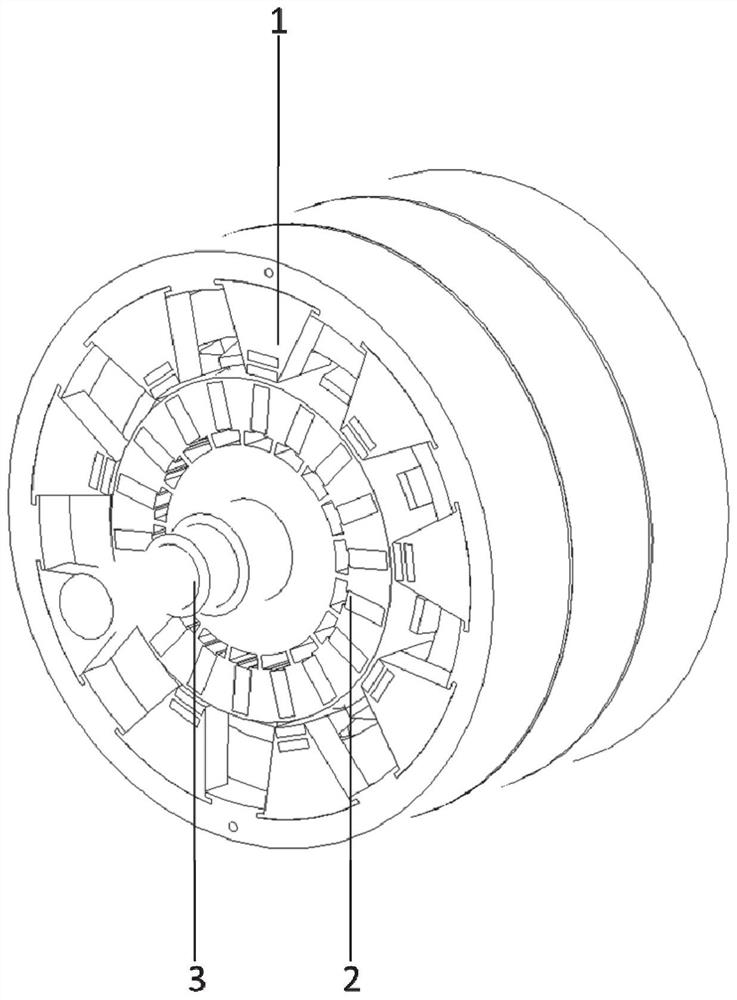
[0073] This embodiment discloses a combined stator core claw pole transverse magnetic flux permanent magnet brushless motor structure, such as figure 1 As shown, it includes a stator 1, a rotor 2 and a rotating shaft 3.

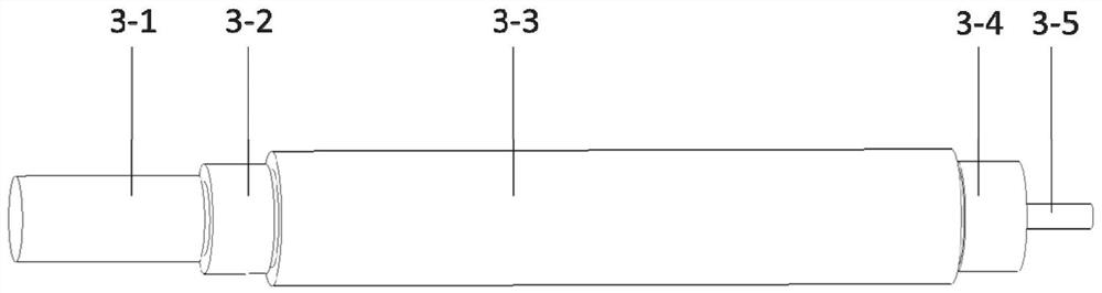
[0074] Rotary shaft 3 plays a key role in motor design and assembly, combined with figure 2 The rotating shaft segment is explained. The rotating shaft 3 includes the shaft extension end 3-1, the front bearing section 3-2, the rotor section 3-3, the rear bearing section 3-4, and the encoder section 3-5.

[0075] Specifically, the shaft extension end 3-1 of the rotating shaft 3 is used to output torque to connect the load; the front bearing section 3-2 is matched with the front bearing, and an interference fit is used during assembly; the rotor section 3-3 is matched with the rotor 2 to realize the torque The transmission from the motor to the rotating shaft; the rear bearing section 3-4 is matched with the rear bearing, and the assembly type adopts interfer...


PUM


Abstract

The present disclosure proposes a combined stator iron core claw pole transverse magnetic flux permanent magnet brushless motor structure and method, including: a rotating shaft, a rotor and a stator sequentially arranged from the inside to the outside; It consists of phase stator modules. Each phase stator module includes a stator yoke, stator teeth and a phase winding coil. The stator teeth are composed of stator tooth tooth bodies and stator tooth tooth shoes. The stator tooth tooth body is partially embedded in the stator yoke. The stator tooth shoe and the stator tooth body have the advantages of high torque density, high efficiency, strong overload capacity, simple manufacturing process and simple driving control mode.

Description

technical field [0001] The present disclosure belongs to the technical field of electric motors, and in particular relates to a structure and a method of a combined stator iron core claw-pole transverse magnetic flux permanent magnet brushless motor. Background technique [0002] The statements in this section merely provide background information related to the present disclosure and do not necessarily constitute prior art. [0003] There is no very strict definition of direct drive motor at present. Its main feature is low speed and high torque. Generally, it refers to a motor whose speed is lower than 500 rpm and can directly drive the load. For a direct drive motor with a design speed below 50 rpm, it is called an ultra-low speed direct drive motor. At present, the direct drive motor has a very wide range of applications in the industrial field, and has gradually begun to play a role in commercial ventilation, industrial production transmission systems, oil field explor...

Claims


Application Information

Patent Timeline
Patent Type & Authority Patents(China)
IPC IPC(8): H02K29/00H02K29/03H02K29/06H02K1/14H02K7/00H02K1/02H02K15/12H02K1/276H02K15/02
CPCH02K29/00H02K29/03H02K29/06H02K1/146H02K7/003H02K1/02H02K15/12H02K1/276H02K1/2766H02K15/02
Inventor 徐衍亮张文晶
Owner SHANDONG UNIV
Why Eureka
Try Eureka