Light emitting module, depth camera and electronic equipment

A depth camera and module technology, applied in the field of optics, can solve problems such as the inability to achieve near-field high precision, reduce the overall uniformity of the image, and affect the accuracy of depth information, etc.

Inactive Publication Date: 2021-05-28
NANCHANG OUFEI BIOLOGICAL IDENTIFICATION TECH
View PDF0 Cites 1 Cited by
  • Summary
  • Abstract
  • Description
  • Claims
  • Application Information

AI Technical Summary

Problems solved by technology

However, the existing TOF scheme has flaws in the arrangement of the light source and the homogenizing sheet, resulting in stripes in the projected spot, which seriously affects the accuracy of the obtained depth information, reduces the overall uniformity of the image, and cannot achieve near-field high precision.

Method used


Image

  • Light emitting module, depth camera and electronic equipment
  • Light emitting module, depth camera and electronic equipment
  • Light emitting module, depth camera and electronic equipment

Examples


Embodiment Construction

[0034] The technical solutions in the embodiments of the present invention will be clearly and completely described below in conjunction with the accompanying drawings in the embodiments of the present invention. Obviously, the described embodiments are only part of the embodiments of the present invention, not all of them. Based on the implementation manners in the present invention, all other implementation manners obtained by persons of ordinary skill in the art without making creative efforts belong to the scope of protection of the present invention.

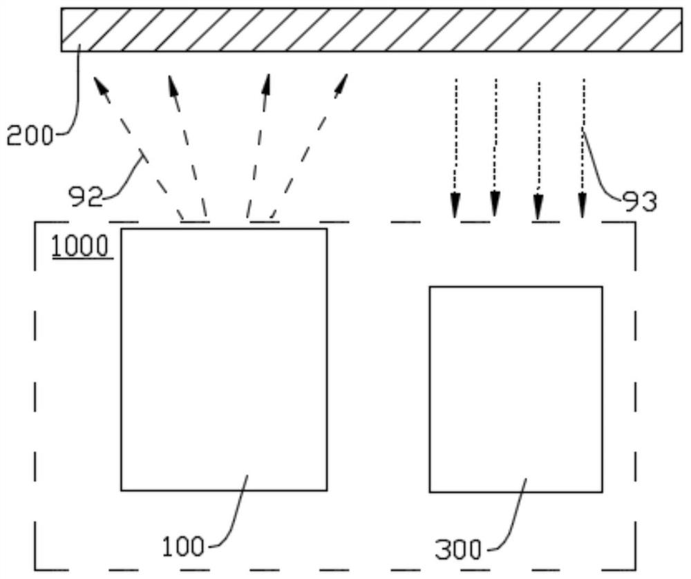
[0035] see figure 1 , the embodiment of the present invention provides a depth camera 1000. The depth camera 1000 can be a video camera, a projector, a camera, a monitoring camera, etc., and can also be applied to an electronic device as a component of the electronic device, such as a camera on a mobile phone, The camera of the time card recorder and the sensor of the somatosensory game console, etc. The depth camera 1000 ...


PUM


Abstract

The invention provides a light emitting module, a depth camera and electronic equipment. The light emitting module comprises a vertical cavity surface emitting laser and a light uniformizing sheet, the vertical cavity surface emitting laser is used for emitting first light to the light uniformizing sheet, the light uniformizing sheet is used for diffusing the first light and uniformly emitting second light to a target object, the vertical cavity surface emitting laser comprises a plurality of light emitting units, the light equalizing sheet is provided with a plurality of micro lenses, and the plurality of light emitting units and/or the plurality of micro lenses are arranged randomly. By reasonably arranging the structures of the vertical cavity surface emitting laser and the light equalizing sheet, the light emitting module emits the second light capable of collecting the information of the target object. Meanwhile, by adopting the random arrangement mode of the multiple light emitting units and/or the multiple micro lenses, resonance is avoided, so that stripes of projected light spots are improved and eliminated, and the light emitting efficiency is improved. The precision of the obtained depth information and the overall uniformity of the image are improve. The invention can be applied to a TOF high-precision application scene.

Description

technical field [0001] The invention belongs to the field of optics, and in particular relates to a light emission module, a depth camera with the light emission module and electronic equipment with the depth camera. Background technique [0002] With the development of science and technology, the depth information collection technology continues to innovate. The depth information collection mainly includes Time of Flight (TOF) solutions, structured light solutions and binocular stereo vision solutions. Compared with the structured light scheme and the binocular stereo vision scheme, the time-of-flight scheme has the advantages of higher multi-angle recognition accuracy, faster recognition speed and wider recognition area. [0003] Nowadays, the TOF scheme is applied to more and more scenarios in front of the terminal. The TOF scheme belongs to the two-way ranging technology. It mainly uses the flight time of the signal to and fro between two asynchronous transceivers to mea...

Claims


Application Information

Patent Timeline
Patent Type & Authority Applications(China)
IPC IPC(8): H04N5/225H04N5/217
CPCH04N23/81H04N23/57H04N23/55
Inventor 成纯森李宗政陈冠宏丁细超
Owner NANCHANG OUFEI BIOLOGICAL IDENTIFICATION TECH
Why Eureka
Try Eureka