Control method for traction force of hybrid four-wheel drive vehicle
A Traction Control, Traction Technology
- Summary
- Abstract
- Description
- Claims
- Application Information
AI Technical Summary
Problems solved by technology
Method used
Image
Examples
Embodiment 1
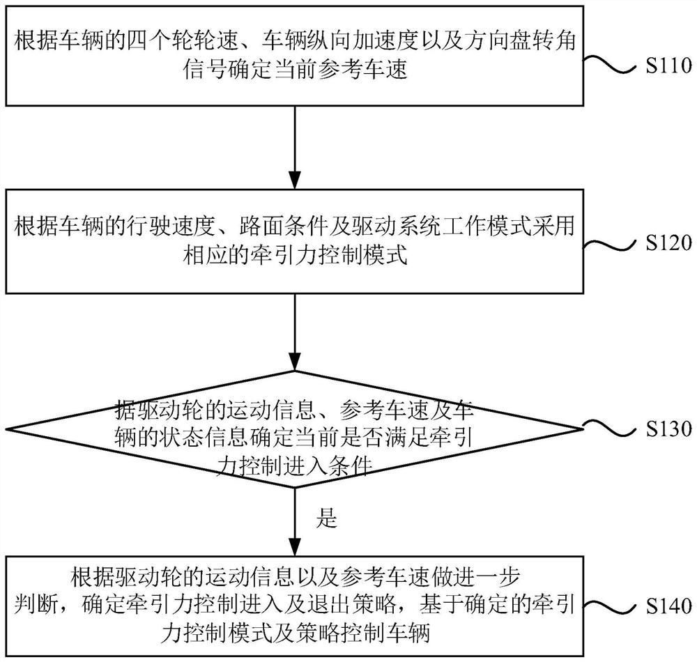
[0056] figure 1 It is a flow chart of a method for controlling the traction force of a hybrid four-wheel drive vehicle provided in Embodiment 1 of the present invention. This embodiment is applicable to the situation where the vehicle traction force is controlled when the vehicle slips. The method can be controlled by the vehicle traction force control device to perform, such as figure 1 As shown, the method specifically includes the following steps:
[0057] Step 110, determine the current reference vehicle speed according to the four wheel speeds of the vehicle, the longitudinal acceleration of the vehicle and the steering wheel angle signal.
[0058] Among them, the current reference vehicle speed can be understood as the speed at which the entire vehicle moves forward. According to the four wheel speeds of the vehicle, the vehicle longitudinal acceleration and the steering wheel angle signal, the vehicle reference speed is calculated by the Kalman filter method.
[0059]...
Embodiment 2
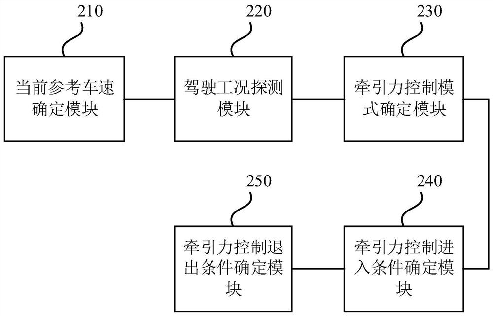
[0135] figure 2It is a schematic structural diagram of a traction force control device for a hybrid four-wheel drive vehicle in Embodiment 2 of the present invention. Such as figure 2 As shown, the device includes:
[0136] The current reference vehicle speed determination module 210 is used to determine the current reference vehicle speed according to the four wheel speeds of the vehicle, the longitudinal acceleration of the vehicle and the operating conditions of the steering wheel angle signal;
[0137] The driving condition detection module 220 is used for receiving and processing the wheel speed signals and wheel acceleration signals sent by the wheel speed sensors of the four wheels, receiving and processing the longitudinal acceleration signals of the vehicle sent by the yaw rate sensors, and receiving and processing the vehicle longitudinal acceleration signals according to the steering wheel Receiving the steering wheel angle signal from the angle sensor and judgi...
Embodiment 3
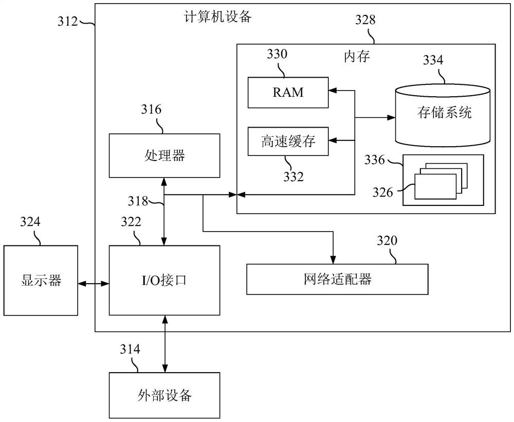
[0185] image 3 It is a schematic structural diagram of a computer device provided by Embodiment 3 of the present invention. image 3 A block diagram of a computer device 312 suitable for implementing embodiments of the invention is shown. image 3 The computer device 312 shown is only an example, and should not impose any limitation on the functions and scope of use of the embodiments of the present invention. Device 312 is a computing device for typical vehicle traction control functions.
[0186] Such as image 3 As shown, computer device 312 takes the form of a general-purpose computing device. Components of computer device 312 may include, but are not limited to: one or more processors 316, storage 328, bus 318 connecting various system components including storage 328 and processor 316.
[0187] Bus 318 represents one or more of several types of bus structures, including a memory bus or memory controller, a peripheral bus, an accelerated graphics port, a processor, o...
PUM
 Abstract
Description
Claims
Application Information
 - R&D
- Intellectual Property
- Life Sciences
- Materials
- Tech Scout
- Unparalleled Data Quality
- Higher Quality Content
- 60% Fewer Hallucinations
Browse by: Latest US Patents, China's latest patents, Technical Efficacy Thesaurus, Application Domain, Technology Topic, Popular Technical Reports.
© 2025 PatSnap. All rights reserved.Legal|Privacy policy|Modern Slavery Act Transparency Statement|Sitemap|About US| Contact US: help@patsnap.com


