High-efficiency electrolytic ozone generating device

An ozone generating device and high-efficiency technology, applied in the electrolysis process, electrolysis components and other directions, can solve the problems of increased electrical conductivity of raw water, large space occupation, large demand for ozone, etc., and achieve high ozone production and high work efficiency. , a large number of effects

Pending Publication Date: 2021-06-01
金华市润达环保科技有限公司
View PDF0 Cites 2 Cited by
  • Summary
  • Abstract
  • Description
  • Claims
  • Application Information

AI Technical Summary

Problems solved by technology

[0005] The purpose of the present invention is to provide a high-efficiency electrolytic ozone generator to solve the problem that the low-voltage electrolytic ozone generator on the market currently proposed by the above-mentioned background technology utilizes a water electrolysis unit to electrolyze water to generate ozone. It is often necessary to use a cathode water tank and an anode water tank. The volume of the device is relatively large. One cathode water tank corresponds to one anode water tank or two anode bottles. It occupies a large space, and the output of ozone production is small and the efficiency is low. It is especially used in public places, It is difficult to meet the large demand for ozone in large-scale cold storage, water supply terminal treatment, etc.; the disadvantages of increasing the conductivity of raw material water and the temperature of PEM electrolysis unit after continuous long-term operation of the equipment; and the continuous consumption of raw material water requires manual real-time observation and addition of raw material water cumbersome process

Method used


Image

  • High-efficiency electrolytic ozone generating device
  • High-efficiency electrolytic ozone generating device
  • High-efficiency electrolytic ozone generating device

Examples


Embodiment Construction

[0029] The following will clearly and completely describe the technical solutions in the embodiments of the present invention with reference to the accompanying drawings in the embodiments of the present invention. Obviously, the described embodiments are only some, not all, embodiments of the present invention.

[0030] In describing the present invention, it should be understood that the terms "upper", "lower", "front", "rear", "left", "right", "top", "bottom", "inner", " The orientation or positional relationship indicated by "outside", etc. is based on the orientation or positional relationship shown in the drawings, and is only for the convenience of describing the present invention and simplifying the description, rather than indicating or implying that the referred device or element must have a specific orientation, so as to Specific orientation configurations and operations, therefore, are not to be construed as limitations on the invention.

[0031] refer to Figure ...


PUM


Abstract

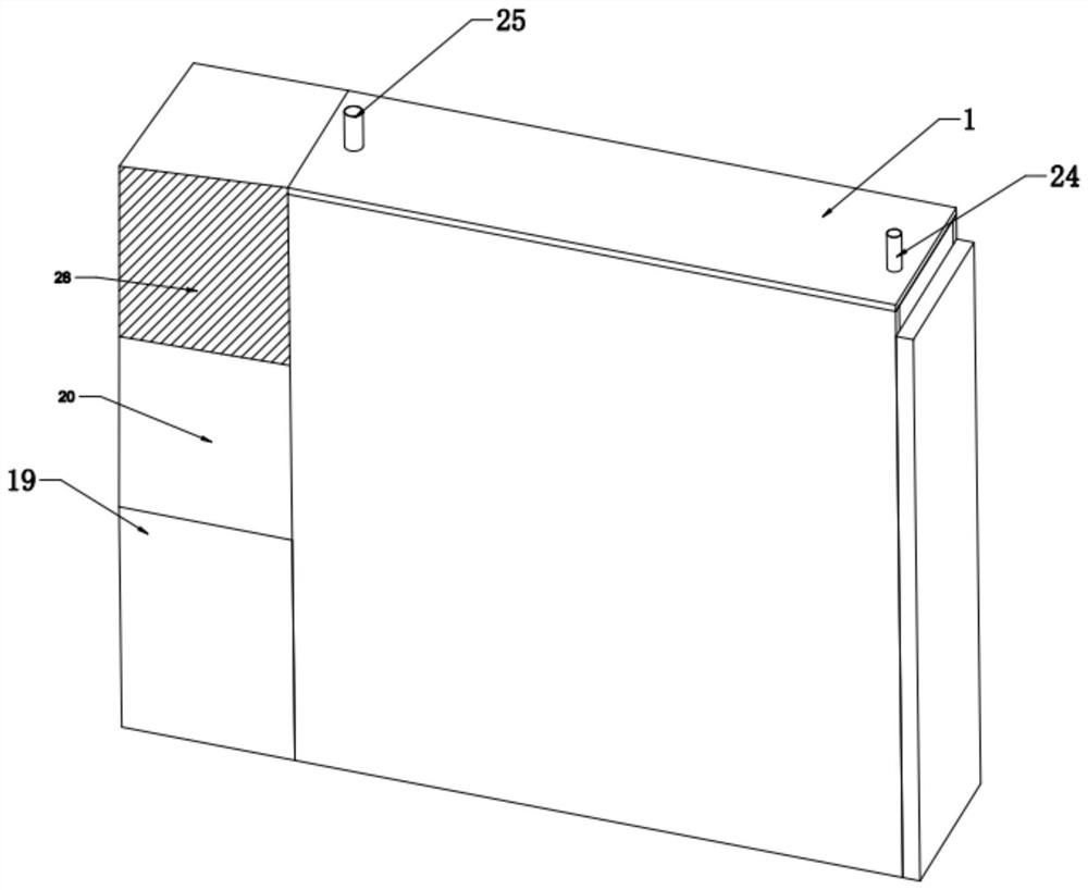
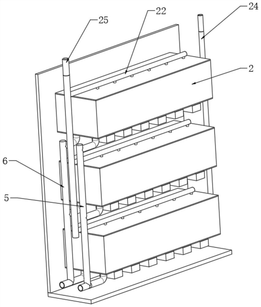
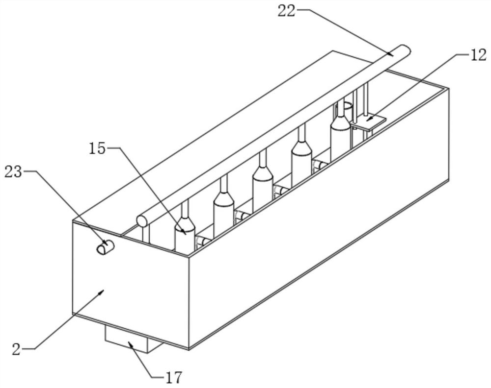
The invention discloses a high-efficiency electrolytic ozone generating device which comprises a box body and a PEM electrolysis unit, a plurality of cathode water tanks are fixedly arranged in the box body, a plurality of water inlet pipes are fixedly inserted into the lower portions of the cathode water tanks correspondingly, and sliding rails are fixedly arranged on the lower end faces of the interiors of the cathode water tanks; a water blocking plate is arranged on the sliding rails in a sliding mode, the water blocking plate is located over the water inlet pipes, a spring is fixedly connected between the water blocking plate and the water inlet pipes, and a liquid level control assembly is fixedly connected to the side wall, away from the water inlet pipes, of the water blocking plate; a plurality ofanode bottles are fixedly arranged in the cathode water tanks; and the side walls of the anode bottles are fixedly connected with a circulating water pipe. The invention relates to the technical field of ozone generation, the anode bottles are arranged in the cathode water tanks, so that the volume of the whole device can be reduced, a plurality of anode bottles can be arranged in one cathode water tank, ozone can be simultaneously generated by the plurality of anode bottles, and the production rate is accelerated.

Description

technical field [0001] The invention relates to the technical field of ozone generation, in particular to a high-efficiency electrolytic ozone generator. Background technique [0002] Ozone has the functions of sterilization, detoxification, and deodorization, and is widely used in various fields such as public health, pharmacy, medical treatment, chemical industry, and agriculture. At present, the methods for generating ozone mainly include corona discharge method and low-voltage electrolysis method. Compared with the corona discharge method, the low-voltage electrolysis method has the advantages of high ozone purity, no nitrogen oxides and other pollution, and is easy to operate and has a high safety factor. [0003] In the prior art, the low-voltage electrolytic ozone generator uses an electrolysis unit to electrolyze water to generate ozone. In this electrolysis method, it is often necessary to use a cathode water tank and an anode water tank. The volume of the device is...

Claims


Application Information

Patent Timeline
Patent Type & Authority Applications(China)
IPC IPC(8): C25B1/13C25B15/08C25B15/021C25B15/027C25B15/033
CPCC25B1/13C25B15/02C25B15/08
Inventor 陆伟宏方琦陈品良方根满张叶朝阳
Owner 金华市润达环保科技有限公司
Why Eureka
Try Eureka