
Aerodynamic engine

Pending Publication Date: 2021-06-01
罗邦琴
View PDF15 Cites 0 Cited by
  • Summary
  • Abstract
  • Description
  • Claims
  • Application Information

AI Technical Summary

Problems solved by technology

[0004] The above prior art is an engine using compressed air as the power source, but it adopts the structure setting of the cylinder driving the crankshaft to output power, which not only completely changes the power system of the existing automobile, but also the practical effect of the cylinder driving structure is not good.

Method used


Image

  • Aerodynamic engine
  • Aerodynamic engine
  • Aerodynamic engine

Examples


Embodiment 1

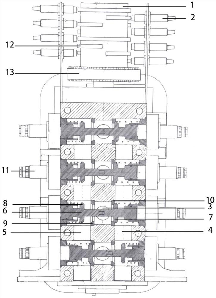
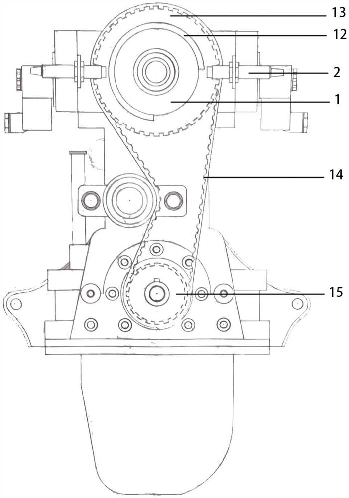
[0028]SeeFigure 1-2The aerodynamic engine characterized in that: includes a signaling wheel (1) connected to the engine crankshaft and the outer signal sensor (2) thereof, and the upper side of each of the engine piston cylinders is provided with a gas eye (3), each A air eye (3) is connected to the air chamber (4) and the vent chamber (5), the intake chamber (4) inputs the gas source, and is located in the air eye (3), a pneumatic valve is provided, and gas is controlled by a pneumatic valve. Eye (3) Connect the intake chamber (4) intake or communication ventilation chamber (5) exhaust, each pneumatic valve work is controlled by the signal wheel (1), the signal sensor (2), and the electronic system.

[0029]On both sides above the air eye (3) are intake charts (4) and exhaust chambers (5), the pneumatic valve stem (6) is horizontally in the intake chamber (4), the air eye (3) above and the venting chamber (5) In the pneumatic valve stem (6), an intake valve cover (7) and an exhaust va...


PUM


Abstract

The invention discloses an aerodynamic engine. The aerodynamic engine is characterized by comprising a signal wheel in transmission connection with an engine crankshaft and a signal sensor on the outer side of the signal wheel, an air hole is formed in the upper side of each engine piston cylinder body, each air hole is communicated with an air inlet chamber and an exhaust chamber, an air source is input into the air inlet chamber, pneumatic valves are arranged on the air holes respectively, the pneumatic valves control the air holes to be communicated with the air inlet chamber for air intake or communicated with the air exhaust chamber for air exhaust, and the work of each pneumatic valve is controlled by the signal wheel, the signal sensor and the electronic system. Compressed air is adopted as energy, the engine works cleanly without pollution, the working cost is low, the energy stock is huge and can be recycled, air inlet and air exhaust are controlled through the signal wheel, the signal sensor and the electronic system structurally, and the engine is accurate, efficient and excellent in performance.

Description

Technical field[0001]The present invention relates to the field of engine technology, and more particularly to a aerodynamic engine.Background technique[0002]At present, all the world is looking for clean, cheap energy to replace traditional energy, and air can be used as a large amount of stock, and there is no contaminated energy to be developed, especially air can be applied to the engine, can solve existing The problem of continuous exhaustion, can also avoid the status quo of traditional energy to continue to pollute the environment and reach green sustainable development.[0003]Chinese patent disclosed in the application number CN201220451709.X discloses an engine, in particular, relates to a variable multi-cylinder aerodynamic engine with compressed air as a power. The variable multi-cylinder aerodynamic engine of the present invention includes: an engine body (1), a cosmetic (20), an intake exhaust electrical control box (30), intake and exhaust gas (40), oil sump ( 50), lowe...

Claims


Application Information

Patent Timeline
IPC IPC(8): F01B1/02F01B1/01F01B25/10
CPCF01B1/01F01B1/02F01B25/10
Inventor 罗邦琴罗永益罗笑笑蒋帼素
Owner 罗邦琴
Learn More