Self-control check valve
A check valve and valve body technology, applied in the direction of control valves, valve details, valve devices, etc., can solve problems such as increased energy consumption, increased pipeline layout costs, and difficulty in controlling the opening or closing time of check valves, etc., to achieve Effects of saving energy consumption and saving additional costs
- Summary
- Abstract
- Description
- Claims
- Application Information
AI Technical Summary
Problems solved by technology
Method used
Image


Examples
Embodiment 1
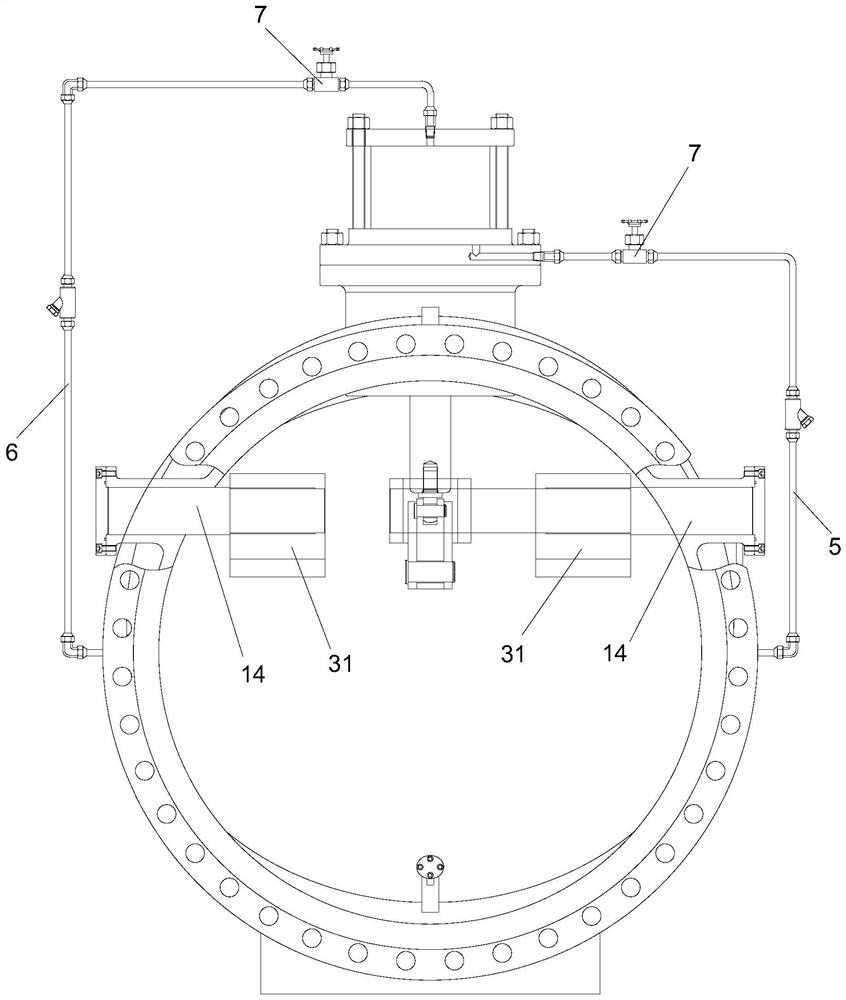
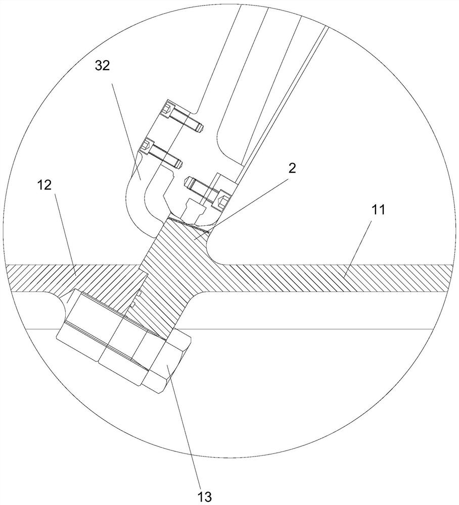
[0030] This embodiment relates to a self-control check valve, refer to figure 1 and figure 2 As shown, it includes a valve body 1, in which a channel for medium circulation is provided, and a valve seat 2 is provided in the channel; the self-control check valve also includes a valve disc 3 and a self-control structure; wherein, the valve The disc 3 is rotatably arranged on the valve body 1, and the valve disc 3 can be rotated to cooperate with the valve seat 2, or disengage from the valve seat 2, and correspondingly block or allow the flow of the medium in the channel.
[0031] The self-control structure includes a piston chamber 101 arranged on the valve body 1, a piston 4 which is slidably arranged in the piston chamber 101 and divides the piston chamber 101 into an upper chamber and a lower chamber, and is arranged at the input end of the channel and the lower chamber. Between the first conduit 5, the second conduit 6 between the output end of the passage and the upper ch...
Embodiment 2
[0046] This embodiment relates to a self-control check valve, which has roughly the same structure as the self-control check valve described in Embodiment 1, the difference lies in: figure 1 and Figure 4 As shown, the piston chamber 101 of this embodiment includes a conical hole section 1011 and a straight hole section 1012 connected in series up and down, and along the direction from top to bottom, the section of the tapered hole section 1011 is gradually reduced, and the tapered hole section 1011 has a small diameter The diameter of the end is equal to the diameter of the straight hole section 1012.
[0047] By setting the structure of the piston cavity 101 according to the above structure, when the piston 4 slides in the piston cavity 101, it will have different sliding speeds. Specifically, the sliding speed of the piston 4 in the tapered hole section 1011 is faster than that of the piston 4. The sliding speed in the straight hole section 1012; that is, when the piston 4...
Embodiment 3
[0051] This embodiment relates to a self-control check valve, which has roughly the same structure as the self-control check valve described in Embodiment 2, the difference lies in: figure 1 As shown, in this embodiment, a water hammer absorption chamber 102 is constructed on the valve body 1, and the top end of the piston rod 41 extends into the piston chamber 101 after passing through the water hammer absorption chamber 102; A number of communication holes are opened on the bottom wall to form the communication between the water hammer absorption chamber 102 and the channel, and the water hammer absorption chamber 102 is provided with a water hammer absorption plate 8, and the water hammer absorption plate 8 is slidingly sleeved On the piston rod 41, the outer periphery of the water hammer absorption plate 8 abuts against the side wall of the water hammer absorption chamber 102, and an elastic Item 9.
[0052] In this example, refer to figure 1 As shown, a mounting part is...
PUM
 Abstract
Description
Claims
Application Information
 - R&D Engineer
- R&D Manager
- IP Professional
- Industry Leading Data Capabilities
- Powerful AI technology
- Patent DNA Extraction
Browse by: Latest US Patents, China's latest patents, Technical Efficacy Thesaurus, Application Domain, Technology Topic.
© 2024 PatSnap. All rights reserved.Legal|Privacy policy|Modern Slavery Act Transparency Statement|Sitemap