High-thermal-conductivity LED lamp

A technology of LED lamps and high thermal conductivity, applied in the field of lighting, can solve the problems of slow heat dissipation of LED lamp beads, uneven heat dissipation surface, and shortened product life, so as to save the PCB assembly process, reduce the light decay rate, and improve the product life. Effect

Active Publication Date: 2021-06-01
SHENZHEN EX LIGHTING TECH HLDG
View PDF8 Cites 0 Cited by
  • Summary
  • Abstract
  • Description
  • Claims
  • Application Information

AI Technical Summary

Problems solved by technology

[0003] In this kind of conventional LED lamps, the PCB and the heat sink are two independent materials. The thermal conductivity of the conventional PCB is low, and if there is a slight Deformation, misalignment of the screws for installing and fixing the PCB, and uneven or unclean heat dissipation surfaces will cause the heat from the LED lamp beads to be exported too slowly when the product is working, which will greatly increase the temperature rise of the LED lamp beads, resulting in Seriously increase the light decay of LED and greatly reduce the life of the product

Method used


Image

  • High-thermal-conductivity LED lamp
  • High-thermal-conductivity LED lamp

Examples


Embodiment 1

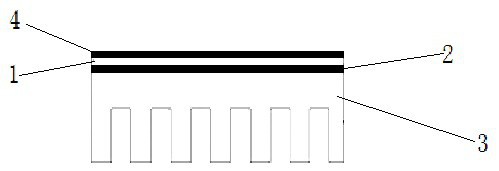
[0026] The preparation method of the high thermal conductivity LED lamp of Example 1 is as follows: directly use the heat sink 3 as the electronic circuit board, directly press the copper layer 1 and the insulating layer 2 on the circuit to the heat sink 3, then etch the circuit, and then apply a resistive layer. Soldering layer 4 and pasting of LED lamp beads; the use of aluminum substrate and heat-conducting material is directly omitted; the heat-conducting path is LED-copper layer 1-insulating layer 2-radiator 3.

[0027] Adopting the structure of Embodiment 1 of the present invention can improve the heat dissipation effect of the product, reduce the pearlescent decay rate of the LED lamp, increase the product life, reduce the difficulty of the product assembly process, and save the PCB assembly process.

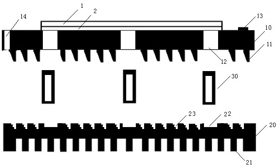
[0028] In the process of trial-manufacturing Example 1, the inventors further found that the above-mentioned process needs to adopt a pressing process, and when the copper...


PUM


Abstract

The invention relates to a high-thermal-conductivity LED lamp, which comprises a solder mask layer (4), a copper layer (1), an insulating layer (2) and a radiator (3) which are sequentially and adjacently arranged from top to bottom. According to the high-thermal-conductivity LED lamp, the heat dissipation effect of a product is improved, the light decay rate of the LED lamp beads is reduced, the service life of the product is prolonged, the assembly process difficulty of the product is reduced, and the PCB assembly process is omitted.

Description

technical field [0001] The present application relates to the lighting field, in particular to a high thermal conductivity LED lamp. Background technique [0002] At present, the main method of heat dissipation for conventional LED lamps on the market is to use aluminum heat sinks to export the heat generated by LED light out of the lamp body through conduction heat dissipation and convection heat dissipation until the heat is dissipated in the surrounding air; the heat conduction path is mainly the heat conduction path It is LED-PCB copper layer-PCB insulation layer-PCB substrate-thermal conductive material-radiator. [0003] In this conventional LED lamp, the PCB and the heat sink are two independent materials. The thermal conductivity of the conventional PCB is low, and if the PCB is slightly deformed during assembly, the screws for installing and fixing the PCB are misaligned, and the heat dissipation surface is uneven. Or when it is not clean, it will cause the heat on...

Claims


Application Information

Patent Timeline
Patent Type & Authority Applications(China)
IPC IPC(8): F21K9/23F21V29/71F21V29/74F21V29/89F21Y115/10
CPCF21K9/23F21V29/717F21V29/74F21V29/89F21Y2115/10
Inventor 刘明宇张锋斌
Owner SHENZHEN EX LIGHTING TECH HLDG
Why Eureka
Try Eureka