Ceiling type air conditioner indoor unit

An air conditioner indoor unit and ceiling-mounted technology, which is applied in air conditioning systems, heating methods, space heating and ventilation, etc., can solve the problems of angle limitation, slow cooling and heating efficiency, small air supply angle, etc., and achieve rapid and balanced temperature adjustment , Improve user experience, expand the effect of air supply angle and range

Pending Publication Date: 2021-06-01
QINGDAO HAIER AIR CONDITIONER GENERAL CORP LTD +1
0 Cites 0 Cited by

AI-Extracted Technical Summary

Problems solved by technology

[0003] The current air conditioner adjustment devices mainly include various types of air conditioners and fans, but the most widely used wall-mounted air conditioners and vertical air conditioners have angle restrictions on the air supply range, and can only achieve one-sided air supply....

Method used

As shown in Figures 1 and 3, the outer peripheral wall of the inner casing 110 is provided with an inner ring 112, and the outer casing 120 is provided with an outer ring 122 that cooperates with the inner ring 112, so that the outer casing 120 is arranged on the inner casing 110 exterior. Preferably, the inner ring 112 is disposed on the upper half of the outer peripheral wall of the inner casing 110 , and the top end of the outer casing 120 is turned inward to form the outer ring 122 . Moreover, the inner ring 112 can actually be a raceway structure, and the inner ring 112 and the outer ring 122 cooperate in a form similar to a rolling bearing, so that the outer shell 120 can be arranged outside the inner shell 110, and The resistance when the rotation driving mechanism drives the outer casing 120 to rotate can be effectively reduced.
[0028] Specifically, as shown in FIGS. 1 to 4 , the first air outlet 111 and the second air outlet 121 can be arranged in a flower shape, so as to enhance the overall aesthetics of the indoor unit 100 of the ceiling-mounted air conditioner. The number of the first air outlet 111 and the second air outlet 121 can be set to 39, and they are evenly arranged in a row of three, a total of 13 rows, so that the indoor unit 100 of the ceiling type air conditioner can blow air. Even air supply in upper, middle, lower and circumferential directions. It should be noted that the specific nu...

Abstract

The invention provides a ceiling type air conditioner indoor unit. The ceiling type air conditioner indoor unit comprises an inner shell, an outer shell, a rotating driving mechanism and a centrifugal fan. A preset number of first air outlet holes are formed in the inner shell. The outer shell is arranged on the outer portion of the inner shell, and second air outlet holes with the positions corresponding to those of the first air outlet holes are formed in the outer shell. The rotating driving mechanism is arranged on the inner shell and is configured to drive the outer shell to rotate, so that the areas of the overlapped parts of the first air outlet holes and the second air outlet holes are changed. The centrifugal fan is arranged in a cavity and is configured to enable air entering the cavity to form wind and blow the wind out through the overlapped parts. According to the ceiling type air conditioner indoor unit, circumferential air outlet can be achieved, the air supply angle and range can be enlarged, rapid and balanced temperature adjustment can be achieved on a room, the situation that a user feels uncomfortable due to narrow-range blowing of airflow is avoided, and the use experience of the user is effectively improved.

Application Domain

Lighting and heating apparatusHeating and ventilation casings/covers +2

Technology Topic

PhysicsEngineering +3

Image

  • Ceiling type air conditioner indoor unit
  • Ceiling type air conditioner indoor unit
  • Ceiling type air conditioner indoor unit

Examples

  • Experimental program(1)

Example Embodiment

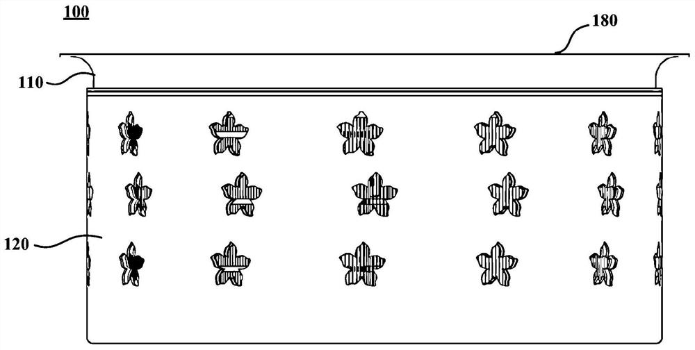
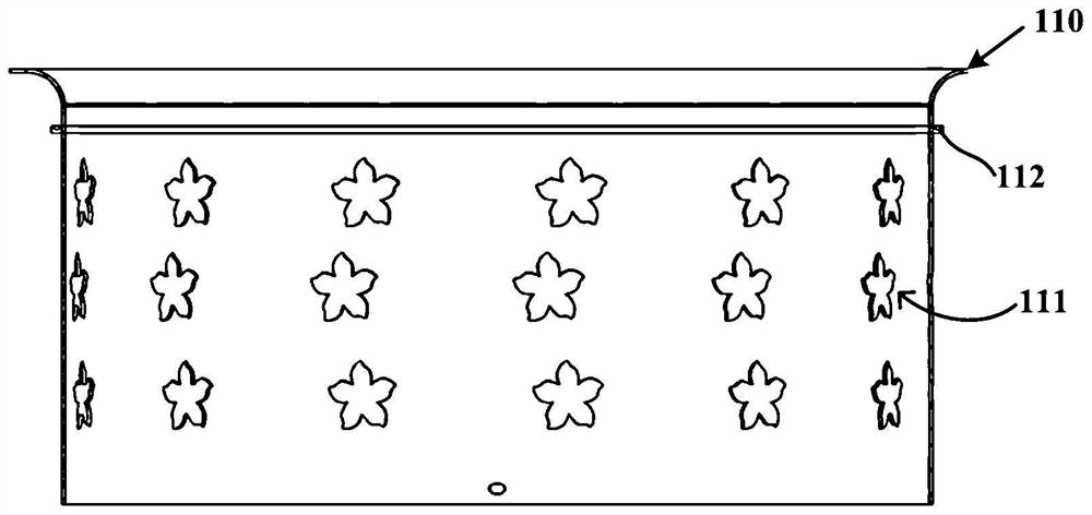
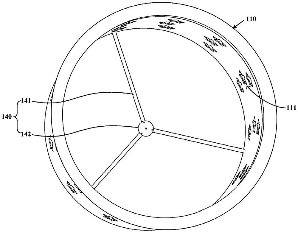
[0026] This embodiment provides an indoor unit of a ceiling-mounted air conditioner, which can realize circumferential air outlet, expand the angle and range of air supply, enable the room to achieve rapid and balanced temperature adjustment, and avoid the discomfort of users caused by the airflow blowing in a small range, effectively improving User experience. figure 1 is a schematic diagram of the overall structure of the ceiling-mounted air conditioner indoor unit 100 according to an embodiment of the present invention, figure 2 Yes figure 1 A structural schematic diagram of the inner casing 110 of the indoor unit 100 of the ceiling-mounted air conditioner shown, image 3 Yes figure 2 The structural schematic view of the inner housing 110 shown in another view, Figure 4 Yes figure 1 The structure schematic diagram of the outer casing 120 of the indoor unit 100 of the ceiling-mounted air conditioner shown, Figure 5 Yes figure 1 The partial structure schematic diagram of the indoor unit 100 of the ceiling type air conditioner shown, Image 6 Yes figure 1 A schematic structural diagram of the evaporator 170 and the centrifugal fan 130 of the indoor unit 100 of the ceiling-mounted air conditioner is shown. like Figure 1 to Figure 6 As shown, the ceiling-mounted air conditioner indoor unit 100 may generally include: an inner casing 110 , an outer casing 120 , a rotary drive mechanism (not shown in the figure) and a centrifugal fan 130 .
[0027] Wherein, a cavity is defined inside the inner casing 110 , and a preset number of first air outlet holes 111 are opened on the inner casing 110 . The outer shell 120 is disposed outside the inner shell 110 , and the second air outlet hole 121 corresponding to the position of the first air outlet hole 111 is opened on the outer shell 120 . In a preferred embodiment, both the inner casing 110 and the outer casing 120 are cylindrical. The number and shape of the first air outlet holes 111 and the second air outlet holes 121 are set correspondingly.
[0028] Specifically, such as Figure 1 to Figure 4 As shown, the first air outlet 111 and the second air outlet 121 can be arranged in a flower shape, so as to improve the overall aesthetics of the indoor unit 100 of the ceiling-mounted air conditioner. The number of the first air outlet 111 and the second air outlet 121 can be set to 39, and they are evenly arranged in a row of three, a total of 13 rows, so that the indoor unit 100 of the ceiling type air conditioner can blow air. Even air supply in upper, middle, lower and circumferential directions. It should be noted that the specific numbers and specific shapes of the above-mentioned first air outlet holes 111 and second air outlet holes 121 are only examples, rather than limiting the present invention. In some other embodiments, the first air outlet holes 111 and the second air outlet holes 121 can also be set in other numbers and shapes.
[0029] The rotation driving mechanism is disposed on the inner housing 110 and is configured to drive the outer housing 120 to rotate so that the area of ​​the overlapping portion of the first air outlet 111 and the second air outlet 121 changes. The centrifugal blower 130 is disposed inside the cavity and is configured to make the air entering the cavity form wind and blow out through the overlapped part. Wherein, the area of ​​the overlapping portion of the first air outlet 111 and the second air outlet 121 is the largest, that is, when the first air outlet 111 and the second air outlet 121 completely overlap, the air output is the largest. When the overlapping area of ​​the first air outlet hole and the second air outlet hole 121 is the smallest, that is, when the first air outlet hole 111 and the second air outlet hole 121 do not overlap at all, the air output is the smallest, and it can be considered that there is almost no wind.
[0030] In the indoor unit 100 of the ceiling-mounted air conditioner of this embodiment, air is discharged through the overlapped portion of the first air outlet 111 of the inner housing 110 and the second air outlet 121 of the outer housing 120, which can realize uniform air outlet in the circumferential direction and expand the air volume. The air supply angle and range enable the room to achieve rapid and balanced temperature adjustment, and avoid the user's discomfort caused by the small-scale blowing of the airflow, effectively improving the user's experience.
[0031] like image 3 and Figure 4 As shown, the bottom of the inner housing 110 is provided with a first bracket 140 , and the bottom of the outer housing 120 is provided with a second bracket 150 . And the rotation drive mechanism includes: a rotation motor (not shown in the figure), fixed on the first support 140, and its rotation shaft is connected with the second support 150, so that the outer casing 120 is driven to rotate through the rotation shaft after opening. In fact, the bottom of the outer casing 120 is lower than the bottom of the inner casing 110, so that the second bracket 150 is below the first bracket 140, so that the top of the rotating motor can be fixed with the first bracket 140, and the bottom of the rotating motor can be fixed. The axis of rotation is fixed to the second bracket 150. Preferably, the rotating motor can be a stepping motor.
[0032]The first bracket 140 includes: a plurality of first spokes 141 and a first hub plate 142 . Wherein, a plurality of first spokes 141 respectively extend from the bottom end of the inner housing 110 to the center of the inner housing 110 . The first hub plate 142 is disposed at the center of the inner shell 110 and connected to a plurality of first spokes 141 , and the rotating motor is fixed on the first hub plate 142 . The second bracket 150 includes: a plurality of second spokes 151 and a second hub plate 152 . Wherein, a plurality of second spokes 151 respectively extend from the bottom end of the outer shell 120 to the center of the outer shell 120 . The second hub plate 152 is disposed at the center of the outer shell 120 and connected to a plurality of second spokes 151 , and the rotation axis is fixed on the second hub plate 152 . It should be noted that the plurality of first spokes 141 and the plurality of second spokes 151 are uniformly distributed.
[0033] In a specific embodiment, for example image 3 and Figure 4 As shown, there are three first spokes 141 and three second spokes 151, and the included angle between any two of the three first spokes 141 is 120°; the included angle between any two of the three second spokes 151 is 120° . The first hub plate 142 and the second hub plate 152 may also be provided with holes for fixing the top of the rotating motor and the rotating shaft, especially the holes for fixing the rotating shaft on the second hub plate 152 match the cross-sectional shape of the rotating shaft set up.
[0034] like figure 1 and image 3 As shown, the outer peripheral wall of the inner housing 110 is provided with an inner ring 112 , and the outer housing 120 is provided with an outer ring 122 matched with the inner ring 112 , so that the outer housing 120 is disposed outside the inner housing 110 . Preferably, the inner ring 112 is disposed on the upper half of the outer peripheral wall of the inner casing 110 , and the top end of the outer casing 120 is turned inward to form the outer ring 122 . Moreover, the inner ring 112 can actually be a raceway structure, and the inner ring 112 and the outer ring 122 cooperate in a form similar to a rolling bearing, so that the outer shell 120 can be arranged outside the inner shell 110, and The resistance when the rotation driving mechanism drives the outer casing 120 to rotate can be effectively reduced.
[0035] Through the relative movement between the outer shell 120 and the inner shell 110, the area of ​​the overlapped part of the first air outlet hole 111 and the second air outlet hole 121 is changed, and the air volume can be effectively adjusted so that the air volume meets the user's demand. match. In a preferred embodiment, the rotation driving mechanism is further configured to: drive the outer casing 120 to rotate, so that the area of ​​the overlapping portion is proportional to the size of the air outlet gear of the indoor unit 100 of the ceiling-type air conditioner. That is to say, the larger the air outlet gear, the larger the area of ​​the overlapping portion of the first air outlet 111 and the second air outlet 121; The area of ​​the overlapping portion of the air outlet holes 121 is smaller.
[0036] like Figure 5 and Image 6 As shown, the ceiling-mounted air conditioner indoor unit 100 may further include: an air intake grill 160 and an evaporator 170 . Wherein, the air intake grille 160 is disposed at the bottom of the outer casing 120, and is provided with a plurality of air intakes 161 to allow external air to enter the cavity. The evaporator 170 is disposed outside the periphery of the centrifugal fan 130 and arranged to exchange heat with the wind generated by the centrifugal fan 130 . Specifically, the shape of the evaporator 170 is matched with the shapes of the inner shell 110 and the outer shell 120 so that the wind after heat exchange passes through the overlapping parts of the first air outlet hole 111 and the second air outlet hole 121 in the circumferential direction evenly. send out.
[0037] In addition, the centrifugal fan 130 may include a centrifugal motor 131 and a centrifugal fan 132 , and the centrifugal motor 131 is disposed on the top of the centrifugal fan 132 and is configured to drive the centrifugal fan 132 to rotate. The indoor unit 100 of the ceiling-mounted air conditioner may further include: a top plate 180 , which is covered on the top of the inner casing 110 and fixed to the ceiling of the room. The centrifugal motor 131 may be fixed on the top plate 180 .
[0038] In the indoor unit 100 of the ceiling-mounted air conditioner of this embodiment, air is discharged through the overlapped portion of the first air outlet 111 of the inner housing 110 and the second air outlet 121 of the outer housing 120, which can realize uniform air outlet in the circumferential direction and expand the air volume. The air supply angle and range enable the room to achieve rapid and balanced temperature adjustment, and avoid the user's discomfort caused by the small-scale blowing of the airflow, effectively improving the user's experience.
[0039] Furthermore, in the indoor unit 100 of the ceiling-mounted air conditioner of this embodiment, through the relative movement between the outer shell 120 and the inner shell 110, the area of ​​the overlapping portion of the first air outlet 111 and the second air outlet 121 can be changed. Changes, and then can effectively adjust the air volume, so that the air volume can match the needs of users.
[0040] Those skilled in the art should understand that, unless otherwise specified, the terms "up", "down", "left", "right", "front", and "rear" in the embodiments of the present invention are used to indicate The terms of orientation or positional relationship are based on the actual use state of the indoor unit 100 of the ceiling-mounted air conditioner. These terms are only for the convenience of describing and understanding the technical solution of the present invention, rather than indicating or implying the referred device or Parts must have a specific orientation and therefore should not be construed as limiting the invention.
[0041] So far, those skilled in the art should appreciate that, although a number of exemplary embodiments of the present invention have been shown and described in detail herein, without departing from the spirit and scope of the present invention, the disclosed embodiments of the present invention can still be used. Many other variations or modifications consistent with the principles of the invention are directly identified or derived from the content. Accordingly, the scope of the present invention should be understood and deemed to cover all such other variations or modifications.

PUM

no PUM

Description & Claims & Application Information

We can also present the details of the Description, Claims and Application information to help users get a comprehensive understanding of the technical details of the patent, such as background art, summary of invention, brief description of drawings, description of embodiments, and other original content. On the other hand, users can also determine the specific scope of protection of the technology through the list of claims; as well as understand the changes in the life cycle of the technology with the presentation of the patent timeline. Login to view more.

Similar technology patents

Method and system for controlling air conditioner

Owner:GD MIDEA AIR-CONDITIONING EQUIP CO LTD +1

Video photographing control device and method, and unmanned aerial vehicle

PendingCN106027896AImprove user experience
Owner:ZEROTECH (BEIJING) INTELLIGENCE TECH CO LTD

Method and system for managing chat messages of instant message temporary session group

InactiveCN103051517AComprehensive management functionsImprove user experience
Owner:BEIJING BAIDU NETCOM SCI & TECH CO LTD
Why Eureka
Try Eureka