Efficient welding die for chip production

A welding mold and high-efficiency technology, applied in welding equipment, auxiliary welding equipment, welding/cutting auxiliary equipment, etc., can solve problems such as uneven pressure and damage of PCB boards

Pending Publication Date: 2021-06-04
张斌
View PDF7 Cites 0 Cited by
  • Summary
  • Abstract
  • Description
  • Claims
  • Application Information

AI Technical Summary

Problems solved by technology

[0006] In view of the problems existing in the prior art, the purpose of the present invention is to provide a high-efficiency welding mold for chip production. In this solution, a servo motor and a driver are set on the mold body, and the PLC controller is programmed by setting parameters on the touch screen. PLC control While sending pulses to the driver, the device receives the signal returned by the pressure sensor. The pulse generates coding parameters, drives the servo motor to rotate, and controls the control force of the PCB board through the resisting mechanism, so that the PCB board can be prevented from being under pressure when the chip is soldered. damage caused by

Method used


Image

  • Efficient welding die for chip production
  • Efficient welding die for chip production
  • Efficient welding die for chip production

Examples


Embodiment

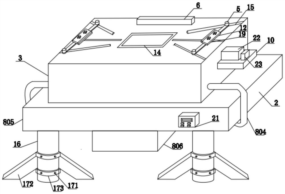
[0046] see Figure 1-13 , this embodiment discloses a high-efficiency welding mold for chip production, including a base 2, the lower end of the base 2 is fixedly connected to the left and right sides of the cylinder 16, and the lower end of the cylinder 16 is provided with a reinforcement mechanism 17, so The upper end of the abutment 2 is fixedly connected with a mold main body 3, and the upper end of the mold main body 3 is fixedly connected with a positioning plate 6, and the left and right sides of the upper end of the mold main body 3 are provided with installation grooves 13, and the installation grooves 13 The inner side of the transmission mechanism 11 is provided with a transmission mechanism 11, the upper end of the transmission mechanism 11 is fixedly connected with a telescopic mechanism 12, the left and right sides of the upper end of the mold main body 3 are provided with chute 15, and the upper end of the mold main body 3 passes through the chute 15 A linkage m...


PUM


Abstract

The invention discloses an efficient welding die for chip production, which comprises a base table, columns are fixedly connected to the left side and the right side of the lower end of the base table, reinforcing mechanisms are arranged at the lower ends of the columns, a touch screen is fixedly connected to the front face of the base table, and a PLC is fixedly connected to the lower end of the base table; a die main body is fixedly connected to the upper end of the base table, a positioning plate is fixedly connected to the upper end of the die main body, mounting grooves are formed in the left side and the right side of the upper end of the die main body, transmission mechanisms are arranged on the inner sides of the mounting grooves, and telescopic mechanisms are fixedly connected to the upper ends of the transmission mechanisms; and sliding grooves are formed in the left side and the right side of the upper end of the die main body correspondingly, and the upper end of the die main body is slidably connected with linkage mechanisms through the sliding grooves. Water is fed through a water guide plate and a water inlet cavity, water is discharged through a sealing plate with a through holes in the filter box, and filtering is conducted through a screen, so that impurities generated in the cooling process can be reduced, and the situation that the heat dissipation effect of the die main body is affected due to pipeline blockage is avoided.

Description

technical field [0001] The invention relates to the technical field of welding molds, in particular to a high-efficiency welding mold for chip production. Background technique [0002] Mold is a basic process equipment widely used in industrial production, and the mold industry is the basic industry of the national economy. In modern industrial production, stamping, forging forming, die-casting forming, extrusion forming, plastic injection or other forming processing methods are widely used for product parts, which are matched with forming molds to form blanks into parts that meet product requirements. All types of tools and products we all use in our daily production and lifestyle, ranging from the base from the machine device, the covering of the equipment equipment, to the small size of a screw, button and the shell of various household appliances, are all closely related to molds. The shape of the mold determines the shape of these products, and the processing quality a...

Claims


Application Information

Patent Timeline
IPC IPC(8): B23K37/04B23K37/00
CPCB23K37/0443B23K37/003
Inventor 张斌
Owner 张斌
Why Eureka
Try Eureka