Fragmentary cloth recycling equipment
A technology for recycling equipment and fabrics, applied in the field of scrap fabric recycling equipment, can solve problems such as easy rolling of scrap fabrics, low cleaning efficiency, pollution of scrap fabrics, etc., to achieve the effect of convenient collection, environmental protection, and labor reduction.
- Summary
- Abstract
- Description
- Claims
- Application Information
AI Technical Summary
Problems solved by technology
Method used
Image
Examples
Embodiment 1
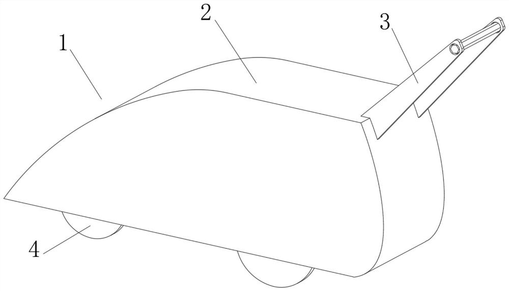
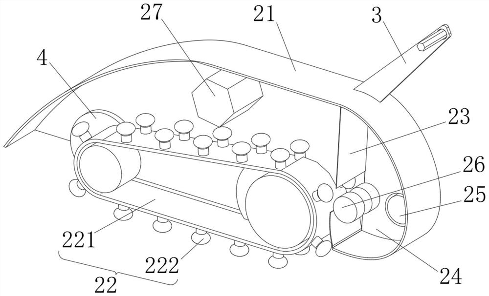
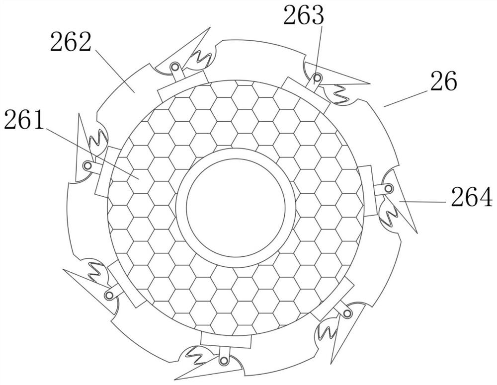
[0036] see Figure 1-3 , the present invention provides a technical solution: a fragmentary cloth recovery equipment, comprising a fragmentary cloth recovery equipment body 1 composed of a recovery box 2, a wheel 3 and a handle 4, the outer side of the wheel 3 is rotationally connected with the inner wall of the recovery box 2 through a bearing, The top of recovery box 2 is fixedly connected with the bottom of handle 4, and recovery box 2 comprises box body 21, and the inside of box body 21 is provided with recovery mechanism 22, and the inner wall of box body 21 is fixedly connected with dividing plate 23, and dividing plate 23 and box body The right side of the inner wall of 21 encloses a recovery cavity 24, and the inside of the box body 21 is rotatably connected with a rotary valve 25. One side of the rotary valve 25 runs through the inner wall of the box body 21 and extends to the inside of the recovery cavity 24, and the interior of the recovery cavity 24 rotates A separ...
Embodiment 2
[0043] see Figure 1-4 On the basis of Embodiment 1, the present invention provides a technical solution: the recoverer 222 includes an elastic airbag 2221, the bottom of the elastic airbag 2221 is fixedly connected with a sliding plate 2222, and the bottom of the sliding plate 2222 is rotatably connected with a rolling bead 2223 , the top of the sliding plate 2222 is fixedly connected with an elastic block 2224 through a telescopic rod, and the inside of the elastic block 2224 is fixedly connected with an air duct 2225 .
[0044] The top of the elastic airbag 2221 runs through the elastic block 2224 and extends to the inside of the air duct 2225. The bottom of the elastic block 2224 is fixedly connected with a lifting plate 2226 through a recovery spring, and the top of the lifting plate 2226 is fixedly connected with an air storage bag 2227.
[0045] The top of the air storage bag 2227 is fixedly connected with the bottom of the elastic block 2224, the top of the air storage...
Embodiment 3
[0048] see Figure 1-5 , on the basis of Embodiment 1 and Embodiment 2, the present invention provides a technical solution: the grabber 2229 includes a grabbing rod 22291, and the top of the grabbing rod 22291 is connected to the inner rotation of the lifting plate 2226 through a rotating seat, and grabbing The inside of the take-up rod 22291 is connected with a rotating block 22292 through a rotating shaft, the right side of the rotating block 22292 is connected with a pressure block 22293 through a rotating ball, and the right side of the pressure block 22293 is fixedly connected with a grasping bar 22294. The outer side of the 22294 is fixedly connected with a grasping leaf 22295, and the end of the grasping bar 22294 away from the pressure block 22293 is fixedly connected with a friction ball 22296.
[0049] When in use, when the grabber 2229 expands outward around the rotating seat, the rotating block 22292 is affected by gravity and partially rotates downward around the...
PUM
 Abstract
Description
Claims
Application Information
 - R&D
- Intellectual Property
- Life Sciences
- Materials
- Tech Scout
- Unparalleled Data Quality
- Higher Quality Content
- 60% Fewer Hallucinations
Browse by: Latest US Patents, China's latest patents, Technical Efficacy Thesaurus, Application Domain, Technology Topic, Popular Technical Reports.
© 2025 PatSnap. All rights reserved.Legal|Privacy policy|Modern Slavery Act Transparency Statement|Sitemap|About US| Contact US: help@patsnap.com


