
Vertical axis fluid energy converting device

An energy conversion device and vertical axis technology, applied in safety devices, wind power generation, transportation and packaging, etc., can solve problems such as expensive, difficult to balance startability and high efficiency, and affect the performance of lift-type blades

Inactive Publication Date: 2021-06-04
周中奇
View PDF4 Cites 3 Cited by
  • Summary
  • Abstract
  • Description
  • Claims
  • Application Information

AI Technical Summary

Problems solved by technology

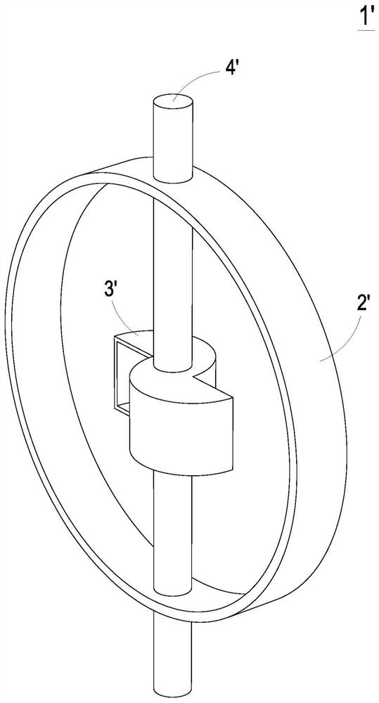
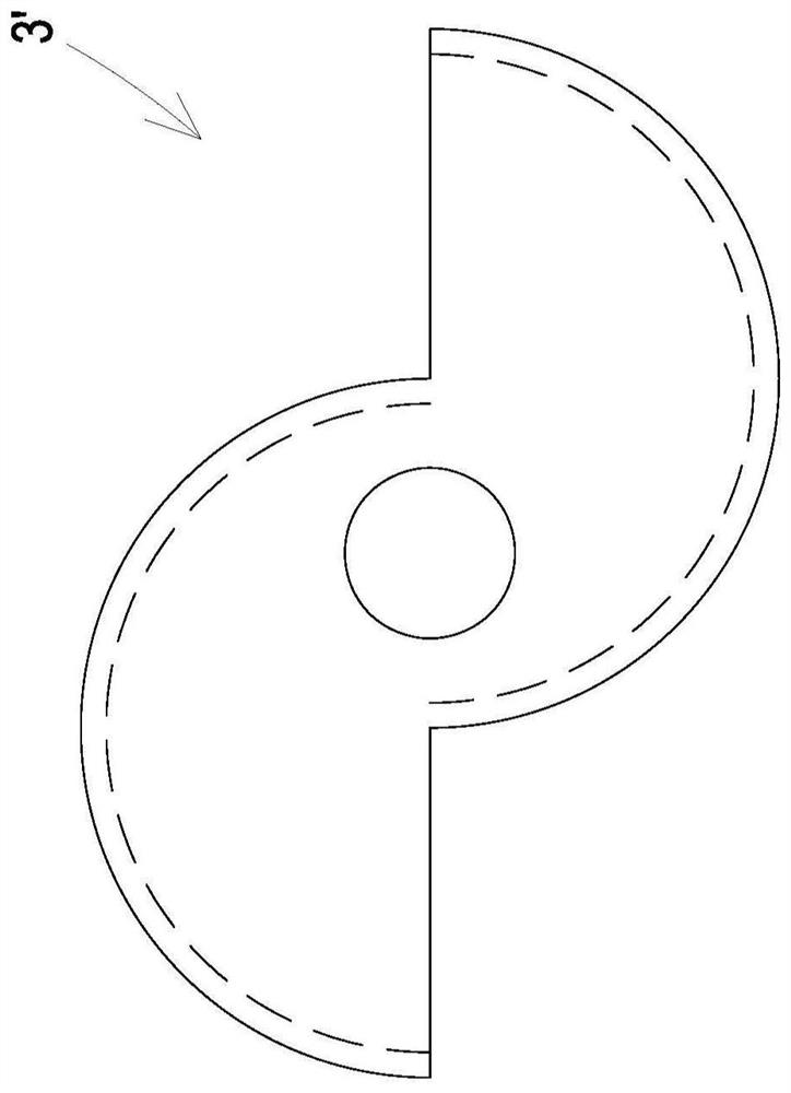
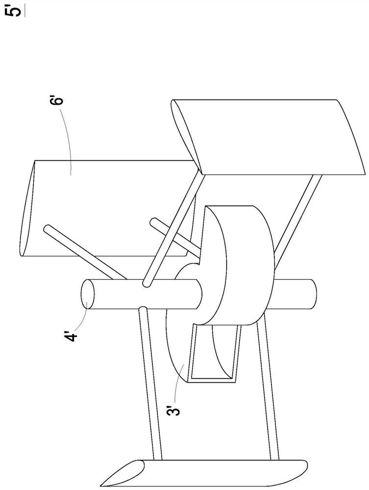
[0006] However, when the radius of gyration of the Savonius resistance blade 3' is designed to be small, such as the aforementioned 1 / 4 ratio, the generated torque is not enough, and it is still unable to self-start at an extremely low fluid flow rate, so the traditional method is to increase The radius or height of the drag-type blade increases the torsion by increasing the cross-sectional area, but it also causes the flow field in the energy conversion device to be more chaotic and affects the performance of the lift-type blade, reducing the overall efficiency of the energy conversion device. Therefore, With the Savonius resistance blade 3' as the starting device, it is difficult to balance the purpose of starting and high efficiency
In addition, when the fluid flow rate is too fast, the large torque produced by the Savonius resistance blade 3' will make the energy conversion device prone to overspeed and cause danger.
[0007] In recent years, there has also been a lift-type blade with a variable pitch design, so that the blade can change its angle according to the direction of fluid flow to start by itself, but this will make the structure more complicated, fragile and expensive due to the increase in moving parts
In addition, installing a starter motor directly on the central shaft to increase the speed is a solution to self-starting, but because the central shaft is connected to the entire energy conversion device, the inertia is not light, and the motor still needs to be equipped with a reduction device to have sufficient torque. Moreover, frequency converters and clutches are required, which not only increase costs, but also cause additional energy consumption. Therefore, vertical axis energy conversion devices have not been widely used successfully for a long time.

Method used


Image

  • Vertical axis fluid energy converting device
  • Vertical axis fluid energy converting device
  • Vertical axis fluid energy converting device

Examples


Embodiment Construction

[0088] Some typical embodiments embodying the features and advantages of the present invention will be described in detail in the description in the following paragraphs. It should be understood that the present invention can have various changes in different ways without departing from the scope of the present invention, and the descriptions and illustrations therein are used for illustration in nature rather than limiting the present invention.

[0089] see Figure 5A , Figure 5B and Figure 6 ,in Figure 5A It is a schematic diagram of the three-dimensional structure of the vertical axis fluid energy conversion device according to the first embodiment of the present invention, Figure 5B for Figure 5A A top view of the vertical axis fluid energy conversion device shown, Figure 6 for Figure 5A Schematic diagram of the operation of the Magnus rotor of the vertical-axis fluid energy conversion device shown. As shown in the figure, when the vertical axis fluid energy...


PUM


Abstract

The invention discloses a vertical axis fluid energy conversion device. The vertical axis fluid energy conversion device includes at least one lift blade and at least one Magnus rotor. A power source drives the Magnus rotor to rotate and the Magnus lift force is produced. The Magnus rotor is connected with a main shaft through a connection component. Consequently, the main shaft is rotated and the lift blade is also revolved. The flow field of the vertical axis fluid energy conversion device is less influenced by the Magnus rotor. The performance of the lift blade is better. The whole efficiency is enhanced. The vertical axis fluid energy conversion device is self-starting through the Magnus rotor. The power source only drives the Magnus rotor to rotate, but not drive the whole device. Therefore, the vertical axis fluid energy conversion device has advantages of low cost and low energy consumption.

Description

technical field [0001] The invention relates to a vertical axis fluid energy conversion device, in particular to a device with a Magnus rotor to drive the main shaft body to rotate by using the Magnus effect, and then drive the lift-type blades to rotate to convert fluid kinetic energy into mechanical energy Vertical axis fluid energy conversion device. Background technique [0002] For the sustainable development of the earth's environment, the development of environmentally friendly green energy has become a trend, and all walks of life have invested a lot of money and manpower in green energy. Among them, fluid power generation devices, such as wind power and ocean current power generation, are due to With the advantages of being inexhaustible and not producing carbon dioxide, the energy conversion device using fluid power has been the direction of development for all walks of life. [0003] Taking wind power generation as an example, the power generation device can be d...

Claims


Application Information

Patent Timeline
Patent Type & Authority Applications(China)
IPC IPC(8): F03D3/02F03D3/06F03D7/06F03B3/12F03B15/00
CPCF03D3/005F03D3/007F03D3/02F03D3/061F03D7/06F03B3/121F03B15/005Y02T70/5236B63H9/02Y02E10/20Y02E10/72F05B2240/201F05B2240/214Y02E10/74F05B2210/16F05B2240/211F03D1/0601
Inventor 周中奇
Owner 周中奇
Learn More