Vacuum residue discharging system

A technology of vacuum and vacuum generating devices, which is applied in the direction of negative pressure pumps, machines/engines, pump components, etc., which can solve the problems of pumping device wear and tear, and achieve the effects of long life, excellent economy, and long maintenance cycle intervals

Pending Publication Date: 2021-06-04
CHINA RAILWAY CONSTR HEAVY IND
View PDF9 Cites 0 Cited by
  • Summary
  • Abstract
  • Description
  • Claims
  • Application Information

AI Technical Summary

Problems solved by technology

[0004] The purpose of the present invention is to provide a vacuum slag discharge system to solve the problem

Method used


Image

  • Vacuum residue discharging system
  • Vacuum residue discharging system
  • Vacuum residue discharging system

Examples


Embodiment 1

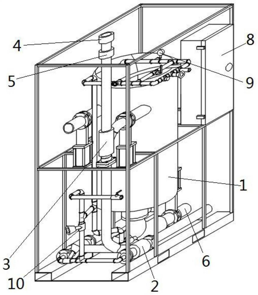
[0040] see Figure 1 to Figure 7 , a vacuum slag removal system, this embodiment is applied to the removal of silt and muck in shield tunnels.

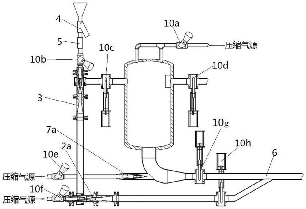
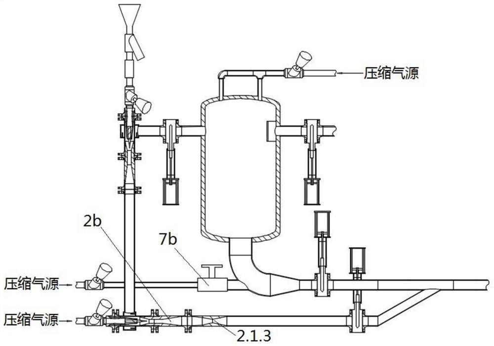
[0041]A vacuum slag discharge system, comprising a slag storage unit, a negative pressure slag suction unit, a positive pressure air supply unit, a slag discharge unit and a compressed air source; the positive pressure air supply unit is respectively connected to the slag storage unit and the compressed air source; The negative pressure slag suction unit is connected to the compressed air source; the negative pressure slag suction unit and the slag discharge unit are both connected to the slag storage unit; the slag storage unit, negative pressure slag suction unit, positive pressure air supply unit, exhaust The slag unit includes a pressure gauge 9 and a valve 10 to monitor the pressure of the vacuum slag discharge system; and to control the on-off of each connecting pipeline.

[0042] see Figure 1 to Figure 3 , the slag storage u...


PUM


Abstract

The invention provides a vacuum residue discharge system. The vacuum residue discharge system involves a residue storage unit, a negative pressure residue suction unit, a positive pressure air supply unit, a residue discharge unit and a compressed air source, wherein the positive pressure air supply unit is connected with the residue storage unit and the compressed air source correspondingly; the negative pressure residue suction unit is connected with the compressed air source; the negative pressure residue suction unit and the residue discharge unit are both connected with the residue storage unit; the residue storage unit comprises a residue storage tank; the negative pressure residue suction unit comprises a vacuum generation device; the vacuum generation device comprises a shell body and a Laval nozzle; the Laval nozzle is embedded into the shell body, and the axis of the Laval nozzle coincides with the axis of the shell body. an annular suction chamber and a first throat part are sequentially arranged in the axis direction of the shell body; a nozzle of the Laval nozzle is located between the annular suction chamber and the first throat part and is used for forming vacuum inside the annular suction chamber; and the annular suction chamber is in communication with the residue storage tank. No moving parts are arranged inside the vacuum generation device, the service life of the parts is long, the maintenance cycle interval of the parts is long, and the economical efficiency is better.

Description

technical field [0001] The invention relates to the field of tunnel construction machinery, in particular to a vacuum slag discharge system. Background technique [0002] The removal of silt and fallen slag in the shield tunnel mainly depends on manual cleaning, which requires a lot of manpower, material resources and time, and the work efficiency is low. Sludge or muck may be ordinary fluid, solid particles, solid-containing fluid, high-viscosity fluid or poisonous gas, etc. In the face of these complex multi-phase media, traditional submersible pumps, pneumatic diaphragm pumps, slurry pumps, etc. all have It cannot be completely cleaned, it is easy to cause air suction, it is necessary to set up a sedimentation tank, and the life of components is greatly affected by the medium and is prone to wear and tear. At the same time, in coal mines, petrochemical and other fields that contain flammable, explosive, toxic and harmful media, etc., the equipment used for feeding, drain...

Claims


Application Information

Patent Timeline
IPC IPC(8): F04F3/00F04F5/20F04F5/44
CPCF04F3/00F04F5/20F04F5/44
Inventor 刘伟张明明李著松叶珂呈刘洁丽方小龙石国强
Owner CHINA RAILWAY CONSTR HEAVY IND
Why Eureka
Try Eureka