Eureka AIR delivers breakthrough ideas for toughest innovation challenges, trusted by R&D personnel around the world.

Inclined detonation experiment system based on gas detonation driving superspeed launching device

A launching device and experimental system technology, which is applied in the field of oblique detonation experimental system, can solve the problems of difficult incoming flow state, the inability to directly measure the mixing ratio of combustible mixed gas and combustion products, impure incoming flow of the nozzle, etc., to achieve accurate measured effect

Active Publication Date: 2021-06-04
INST OF MECHANICS - CHINESE ACAD OF SCI
View PDF6 Cites 7 Cited by
  • Summary
  • Abstract
  • Description
  • Claims
  • Application Information

AI Technical Summary

Problems solved by technology

[0004] When the scheme of mixing in front of the nozzle before the start of the wind tunnel is adopted, during the compression process of the combustible mixture in the wind tunnel, due to the effect of high pressure and high temperature, the combustible mixture will be ignited in advance, and the nozzle may appear during this process. The problem of impure flow, the incoming flow contains both flammable mixed gas and combustion products, and the mixing ratio of flammable mixed gas and combustion products cannot be directly measured, which affects the analysis of experimental results
Injecting fuel after the nozzle can avoid the pre-ignition of the combustible mixture, but because the mixing process of the fuel in the high-speed airflow cannot be directly measured, and the degree of mixing of the combustible gas cannot be directly evaluated, it is very difficult to determine the state of the incoming flow in the experiment, thus Observation and research on experimental phenomena

Method used


Image

  • Inclined detonation experiment system based on gas detonation driving superspeed launching device
  • Inclined detonation experiment system based on gas detonation driving superspeed launching device

Examples


Embodiment Construction

[0044] In order to more clearly understand the above objects, features and advantages of the present invention, the present invention will be further described in detail below in conjunction with the accompanying drawings and embodiments. It should be understood that the described embodiments are some, not all, embodiments of the present invention. The following examples are only used to explain the present invention, but not to limit the present invention. All other embodiments obtained by those skilled in the art based on the described embodiments of the present invention belong to the protection scope of the present invention. Unless otherwise specified, the technical means used in the embodiments are conventional means well known to those skilled in the art.

[0045]It should be noted that in this article, relative terms such as "first" and "second" are only used to distinguish one entity or operation from another entity or operation, and do not necessarily require or imp...


PUM


Abstract

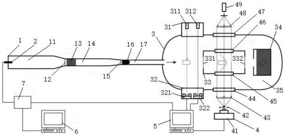
The invention relates to the technical field of combustible gas detonation experiment devices, and provides an inclined detonation experiment system based on a gas detonation driving superspeed launching device. A secondary light gas gun unit is included, the secondary light gas gun unit is connected with an inclined detonation experiment cabin unit and an igniter, the inclined detonation experiment cabin unit is provided with a high-speed photography system, the inclined detonation experiment cabin unit is filled with combustible mixed gas before an experiment is started, and the igniter, the inclined detonation experiment cabin unit and the high-speed photography system are controlled by a computer system; and before the experiment is started, the inclined detonation experiment cabin unit is filled with combustible mixed gas according to a preset working condition and is statically placed, so that the state of the combustible mixed gas is accurately controlled, the combustible mixed gas does not react before the experiment is started, the property of the combustible mixed gas is accurately measured, the purity degree and sufficient and uniform mixing of the combustible mixed gas are guaranteed, and the detonation process of inclined detonation is observed through the high-speed photography system.

Description

technical field [0001] The invention relates to the technical field of combustible gas detonation experimental devices, in particular to an oblique detonation experimental system based on a gas detonation-driven ultra-high-speed launching device. Background technique [0002] Detonation is a chemical reaction transport process accompanied by a large amount of energy release. The chemical reaction process in a detonation releases energy at a high rate. Therefore, the detonation experiment is an important basic experimental research in related scientific research fields. [0003] In the oblique detonation experimental method in the prior art, after the combustible gas is accelerated to a high speed by using a wind tunnel, the gas mixture is induced to detonate by a shock wave on the surface of the model. In this experimental method, the common mixing schemes of the combustible gas mixture include mixing in front of the nozzle before the start of the wind tunnel, and injectin...

Claims


Application Information

Patent Timeline
Patent Type & Authority Applications(China)
IPC IPC(8): F42B35/00
CPCF42B35/00
Inventor 汪球尚甲豪魏炳忱赵伟李进平
Owner INST OF MECHANICS - CHINESE ACAD OF SCI
Why Eureka
Eureka Blog
Learn More