Compression wave observation experiment device in single-cavitation flow field

An experimental device and compression wave technology, which can be used in measurement devices, fluid dynamics tests, and testing of machine/structural components. The effect of high sensitivity and integration

Inactive Publication Date: 2021-06-04
BEIJING INSTITUTE OF TECHNOLOGYGY
View PDF3 Cites 4 Cited by
  • Summary
  • Abstract
  • Description
  • Claims
  • Application Information

AI Technical Summary

Problems solved by technology

However, ordinary high-speed cameras have obvious deficiencies in capturing compressional waves induced by cavitation collapse: insufficient sensitivity to weaker compressi...

Method used


Image

  • Compression wave observation experiment device in single-cavitation flow field
  • Compression wave observation experiment device in single-cavitation flow field
  • Compression wave observation experiment device in single-cavitation flow field

Examples


Embodiment Construction

[0048] The present invention will be described in detail below with reference to the accompanying drawings and examples.

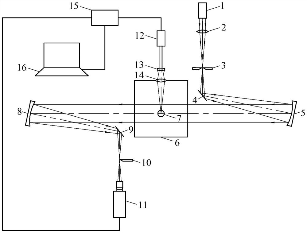
[0049] A compression wave observation experimental device in a single cavity flow field disclosed in this embodiment mainly consists of a parallel continuous light source 1, a No. 1 focusing lens 2, a slit 3, a No. 1 reflector 4, a collimating mirror 5, and an experimental water tank 6 , laser cavity 7, focusing mirror 8, No. 2 reflector 9, knife edge 10, high-speed camera 11, pulse laser 12, beam expander 13, No. 2 focusing lens 14, synchrometer 15, and computer 16. The parallel continuous light source 1 produces parallel light rays and is used as a light source for an optical system. The No. 1 focusing lens 2 focuses the parallel light generated by the parallel continuous light source to the slit 3 . The position of the slit 3 is set at the focal point of the focused light. The No. 1 reflector 4 is arranged behind the slit 3 , and reflects the divergen...


PUM

PropertyMeasurementUnit
Wavelengthaaaaaaaaaa
Diameteraaaaaaaaaa

Abstract

The invention discloses a compression wave observation experiment device in a single-cavitation flow field, and belongs to the field of cavitation dynamics. The device comprises a parallel continuous light source, an optical assembly, an experimental water tank, a high-speed camera, a pulse laser, a synchronizer, a computer and an image processing module. Parallel light generated by the parallel continuous light source irradiates the experimental water tank after passing through the optical assembly; the light source assembly enables the imaging picture of the high-speed camera to be uniformly darkened; the pulse laser induces liquid in the experimental water tank to generate laser cavitation bubbles; the synchronizer triggers the pulse laser and the high-speed camera to work synchronously, and images shot by the high-speed camera are stored by the computer; and the image processing module calculates the gray value change intensity and change direction of the image through a convolution kernel operator so as to extract the wavefront contour of the compression wave and calculate the propagation speed and position of the compression wave. According to the invention, the position and speed information of the compression wave can be quantitatively extracted, and an experimental basis is provided for comprehensive analysis and research of cavitation flow field wave system characteristics, cavitation collapse energy conversion and cavitation erosion failure mechanisms.

Description

technical field [0001] The invention relates to a compression wave observation experiment device in a single cavity flow field, which belongs to the field of cavity dynamics. Background technique [0002] As a common hydrodynamic phenomenon, cavitation has obvious three-dimensional flow characteristics and violent unsteady characteristics, and widely exists in hydraulic machinery, industry, and medicine. Cavitation collapse will cause structural vibration, noise, and fatigue damage. There are two main reasons for this: one is the high-speed jet formed by asymmetric contraction during the evolution of the near-wall region of the cavitation, and the other is the final stage of cavitation collapse. A high-energy shock wave that is generated and radiated outward. Studies have shown that the cavitation effect induced by cavitation high-speed jets is relatively weak: only when the distance between the center of the cavitation and the boundary is very small (less than 0.7 times th...

Claims


Application Information

Patent Timeline
IPC IPC(8): G01M10/00
CPCG01M10/00
Inventor 张敏弟黄国豪郑辰韩磊谭镇坤黄彪
Owner BEIJING INSTITUTE OF TECHNOLOGYGY
Why Eureka
Try Eureka