
Multi-point synchronous longitudinal differential protection direction test system and method

A technology of longitudinal differential protection and test system, which is applied in the field of electric power engineering, can solve problems such as small power flow in closing ring, difficulty in adjustment of longitudinal differential protection, large protection CT transformation ratio, etc., so as to improve operation and maintenance efficiency and promote smooth operation Implement and solve the effect of labor intensity

Pending Publication Date: 2021-06-04
STATE GRID SHANDONG ELECTRIC POWER +1
View PDF5 Cites 0 Cited by
  • Summary
  • Abstract
  • Description
  • Claims
  • Application Information

AI Technical Summary

Problems solved by technology

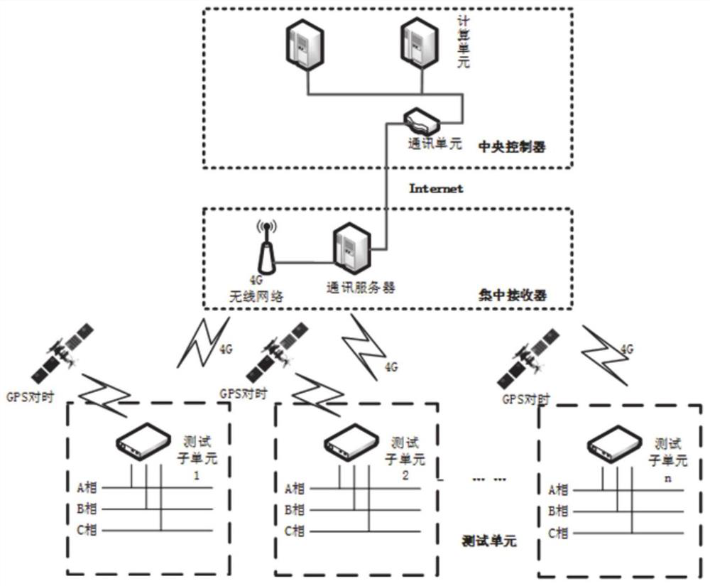
[0005] In order to solve the deficiencies of the existing technology, the present disclosure provides a multi-point synchronous longitudinal differential protection direction testing system and method, which can solve the difficulties in adjusting the longitudinal differential protection due to the power grid mode, the small power flow of the ring closure, and the protection CT ratio Large or single power supply substations with light loads cannot complete the direction measurement problem, and can verify the correctness of the secondary circuit wiring of the longitudinal differential protection current

Method used


Image

  • Multi-point synchronous longitudinal differential protection direction test system and method
  • Multi-point synchronous longitudinal differential protection direction test system and method
  • Multi-point synchronous longitudinal differential protection direction test system and method

Examples


Embodiment 1

[0042] The traditional substation relay protection system adopts the inspection method of single node exclusion. Its inspection method is relatively simple. It mainly uses the relay protection tester to connect the voltage and current test line with the relay protection device of the substation, and then relays Input analog voltage and current into the electrical protection device to detect the operation effect of the substation relay protection system. This detection method can detect the technical performance of the relay protection device and the logic integrity of the secondary circuit.

[0043] The new substation of the power supply company needs to verify the correctness of the wiring of the relay protection system of the substation before it is put into operation. The protection system of the remote switching machine circuit breaker is verified. The distance between different switches in the substation is about tens of meters, and the distance between the switch in the ...


PUM


Abstract

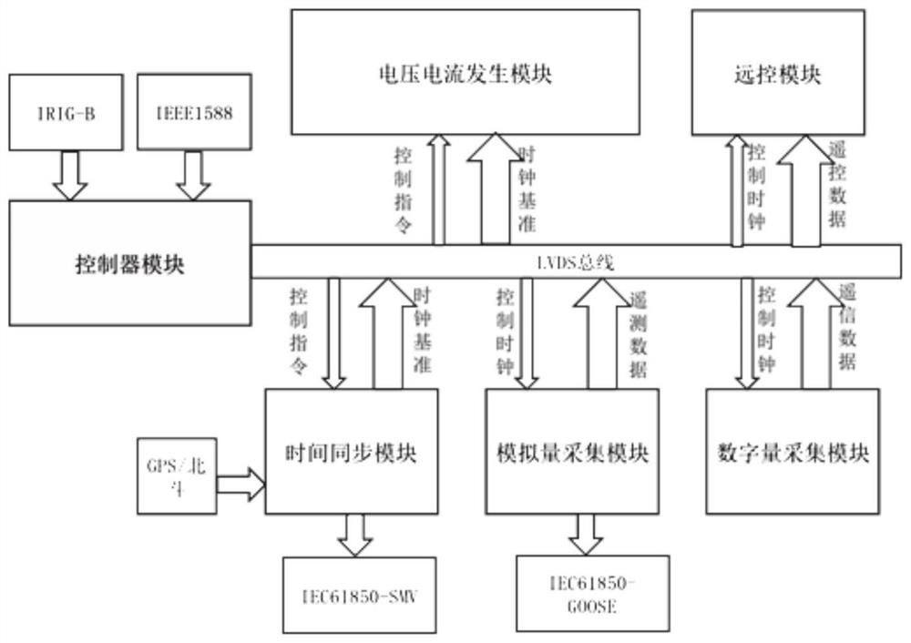
The invention provides a multi-point synchronous longitudinal differential protection direction test system and method. The system comprises a centralized receiver, a central controller, and at least two test subunits, and each test subunit communicates with the central controller through the centralized controller; after each test subunit receives the command of a calculation unit, voltage and current signals with specific amplitudes and phases are synchronously generated at a specific moment, and the wiring correctness of a protection system of a transformer substation switch circuit breaker is verified; all the test subunits send synchronous power grid information obtained through testing to the centralized controller, and the centralized controller calculates and identifies the longitudinal differential protection direction by comparing synchronous power grid data information collected by all the test subunits. The problem that longitudinal differential protection cannot complete direction measurement due to the fact that the power grid mode is difficult to adjust, the loop closing power flow is small, the protection CT transformation ratio is large or the load of a single-power-supply incoming line transformer substation is light can be solved, and the wiring correctness of a longitudinal differential protection current secondary circuit can be verified.

Description

technical field [0001] The disclosure relates to the technical field of electric power engineering, in particular to a multi-point synchronous longitudinal differential protection direction testing system and method. Background technique [0002] The statements in this section merely provide background information related to the present disclosure and may not necessarily constitute prior art. [0003] Power line longitudinal protection, busbar and transformer differential protection, distance protection and directional protection all need to verify the correctness of wiring when new equipment is put into operation or the current circuit changes. [0004] The inventors found that the existing voltage and current generating device can verify a certain switch or a certain point, and cannot verify the protection system of the remote switch machine circuit breaker. The distance between different switches in the substation is about tens of meters, and the substation The distance ...

Claims


Application Information

Patent Timeline
IPC IPC(8): G01R31/00G01R31/67H02H7/26
CPCG01R31/00G01R31/67H02H7/26
Inventor 孔宁彭红霞侯广松甄颖曾宪振程昭龙甄晓琨胡国华祝高乐李明李中原
Owner STATE GRID SHANDONG ELECTRIC POWER
Learn More