
Noise suppression filter and method for manufacturing noise suppression filter

A noise suppression and filter technology, applied in the field of filters, can solve problems such as interference, increased differential mode signal loss, increased volume and cost of multilayer circuit boards, etc.

Active Publication Date: 2022-04-05
INVENTEC PUDONG TECH CORPOARTION +1
View PDF6 Cites 0 Cited by
  • Summary
  • Abstract
  • Description
  • Claims
  • Application Information

AI Technical Summary

Problems solved by technology

[0003] However, in differential transmission, there will still be interference from common mode noise
In the prior art, common mode choke coils are often used to suppress common mode noise. However, the volume of the common mode choke coil is too large, and the magnetic material used in the common mode choke coil is easy to loss, so it cannot be used in high frequency circuits
In addition, there is also a prior art method of using a mushroom-shaped resonant structure (mushroom structure) to suppress common-mode noise. However, the mushroom-shaped resonant structure requires more signal circuit layers, which will increase the volume and cost of the multilayer circuit board.
Furthermore, in order to meet the filtering frequency required by the second resonant mode, the mushroom-shaped resonant structure needs to increase the electrical length through longer meandering traces, but too many segments of meandering traces will also increase the differential mode Signal loss, so it faces many difficulties in design

Method used


Image

  • Noise suppression filter and method for manufacturing noise suppression filter
  • Noise suppression filter and method for manufacturing noise suppression filter
  • Noise suppression filter and method for manufacturing noise suppression filter

Examples


Embodiment Construction

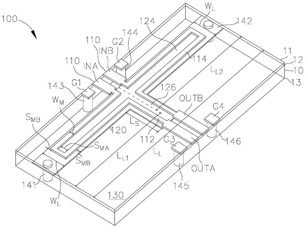
[0038] figure 1 is a schematic diagram of a noise suppression filter 100 according to an embodiment of the present invention. The noise suppression filter 100 may include a differential transmission line set 110 , a resonator 120 and a ground plane 130 . The differential transmission line group 110, the resonator 120 and the ground plane 130 can be respectively arranged on the first circuit layer 11, the second circuit layer 12 and the third circuit layer 13 of the multilayer circuit board 10, and the second circuit layer 12 is arranged on Between the first circuit layer 11 and the third circuit layer 13 .

[0039] exist figure 1 Among them, the resonator 120 has a first long arm 122 , a second long arm 124 and a short arm 126 . The first long arm 122 , the second long arm 124 and the short arm 126 may extend from the same point to form a symmetrical convex shape. For example, the first long arm 122 and the second long arm 124 can be connected to form a straight block, and...


PUM


Abstract

The noise suppressing filter includes a differential transmission line group, a resonator and a grounding plane respectively arranged on the first circuit layer, the second circuit layer and the third circuit layer of the multilayer circuit board. The resonator has a first long arm, a second long arm and a short arm, and the first long arm, the second long arm and the short arm extend from the same point to form a symmetrical convex shape. The ground plane is coupled to the terminal of the first long arm and the terminal of the second long arm through the two through holes. The differential transmission line set includes a first meandering line and a second meandering line, the first meandering line is arranged from the first input end along the inner edge of the first long arm and the inner side of the first side of the short arm and connected to The first output end, and the second meandering line is arranged from the second input end along the inner edge of the second long arm and the inner side of the second side of the short arm and connected to the second output end.

Description

technical field [0001] The invention relates to a filter, in particular to a filter for suppressing common mode noise. Background technique [0002] In differential transmission, the signal transmitter will transmit two signals with the same amplitude and opposite phase through two transmission lines, and the signal receiver will judge the logic sent by the signal transmitter based on the voltage difference between the two signals. state. Since the signal receiving end judges the logic state of the signal based on the voltage difference between the two signals rather than the voltage of the two signals themselves, the influence of the noise in the environment on the two signals will cancel each other out, making the differential transmission Has better noise immunity. [0003] However, in differential transmission, it will still be interfered by common mode noise. In the prior art, common mode choke coils are often used to suppress common mode noise. However, the volume o...

Claims


Application Information

Patent Timeline
Patent Type & Authority Patents(China)
IPC IPC(8): H01P1/20H01P11/00
CPCH01P1/20H01P11/00H02M1/123H01P1/2039H01P3/026H05K1/0245H05K1/16H05K1/0224H05K1/0298H03H9/6423H05K1/0225H03H1/0007H03H7/427H03H2001/0085
Inventor 陈彦豪郑又豪林丁丙
Owner INVENTEC PUDONG TECH CORPOARTION
Learn More