
Excitation mode of gas turbine

An excitation method and technology for gas turbines, which are applied to control generators, control generators and electrical components through magnetic field changes, and can solve problems such as the impact on the life of related electrical equipment, long construction periods, and impact on unit operation.

Pending Publication Date: 2021-06-04
深圳南山热电股份有限公司
View PDF6 Cites 0 Cited by
  • Summary
  • Abstract
  • Description
  • Claims
  • Application Information

AI Technical Summary

Problems solved by technology

However, once the high-voltage excitation transformer at the generator end fails, it usually takes a long time for maintenance, which directly affects the operation of the unit.
And the 9E gas turbine is usually used as a peak-shaving unit, and the peak-shaving of the power grid is carried out through the start-up and shutdown units, so frequent start-up and stop-off have a great impact on the life of related electrical equipment

Method used


Image

  • Excitation mode of gas turbine
  • Excitation mode of gas turbine

Examples


Embodiment 1

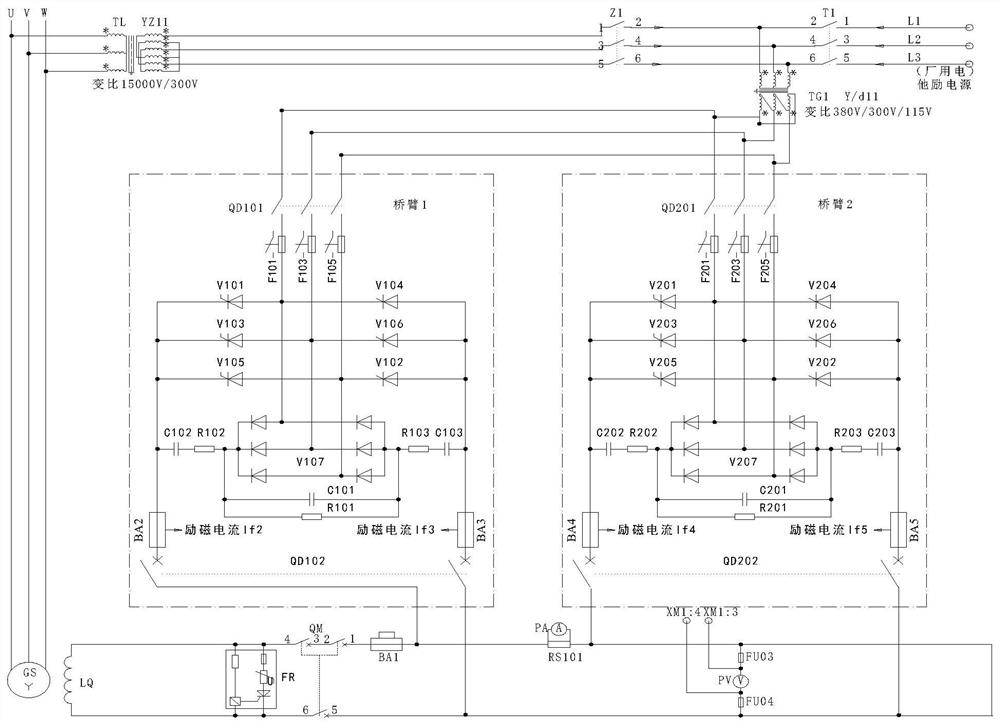
[0021] see figure 1 , an embodiment before transformation: Take #10 gas turbine generator unit of Nanshan Thermal Power Plant as an example: #10 gas turbine adopts TA30-131 generator produced by GE, and the generator excitation system adopts two-machine brushless excitation mode, and the excitation The regulator is provided by Tianjin Ruixin Chuanghe Electric Co., Ltd., the model is FWLZ-E / 1DW. Such as figure 1 As shown, the original excitation system is mainly composed of exciter LQ, excitation regulator, high voltage excitation transformer TL, low voltage excitation transformer TG and excitation current measurement circuit.

[0022] The exciter LQ shown uses a three-phase AC brushless exciter. The three-phase AC output from the static magnetic field and armature rotation is rectified into DC by the coaxial rotating three-phase rotary rectifier and sent to the power generator. The machine field winding provides generator excitation.

[0023] The excitation regulators shown...

Embodiment 2

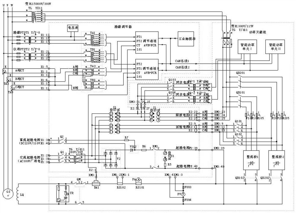
[0028] see figure 2 , an embodiment provided by the present invention: an excitation method of a gas turbine, the low-voltage excitation transformer TG of the gas turbine is replaced by a low-voltage excitation transformer TG1, and the low-voltage excitation transformer TG1 is a double-tap excitation transformer on the primary side; the high-voltage excitation transformer TL A circuit breaker Z1 is added to the output terminal of the secondary side of the circuit breaker, which is connected to the primary side tap 1 of the low-voltage excitation transformer TG through the circuit breaker Z1. ;In addition, one line of factory power is used as the separate excitation power supply, which is connected to the primary side tap 2 of the low-voltage excitation transformer TG1 through the circuit breaker T1. The voltage of the primary side tap 2 is 380V, and the separate excitation excitation power is provided after being transformed by the low-voltage excitation transformer TG1. The ...


PUM


Abstract

The invention discloses an excitation mode of a gas turbine. The mode comprises the steps: replacing a low-voltage excitation transformer TG of the gas turbine with a low-voltage excitation transformer TG1, wherein the low-voltage excitation transformer TG1 is a primary side double-tap excitation transformer; arranging a circuit breaker Z1 additionally at the secondary side output end of the high-voltage exciting transformer TL, and enabling the high-voltage exciting transformer TL to be connected to a primary side tap 1 of the low-voltage exciting transformer TG through the circuit breaker Z1, wherein the voltage of the primary side tap 1 is 300V; transforming the voltage by the low-voltage exciting transformer TG1 and then providing a self-shunt excitation power supply; in addition, leading a path of auxiliary power to serve as a separate excitation power supply, and connecting the separate excitation power supply to a primary side tap 2 of the low-voltage exciting transformer TG1 through a circuit breaker T1, wherein the voltage of the primary side tap 2 is 380V, and the secondary excitation power supply is provided after the voltage transformation of the primary side tap 2 through the low-voltage exciting transformer TG1. The method has the advantages that an excitation mode of rapidly switching from self-shunt excitation to station service separate excitation is provided, when the self-shunt excitation system of the gas turbine unit breaks down, the station service separate excitation mode can be switched within a short time, and the operation reliability of the unit is effectively improved.

Description

technical field [0001] The invention relates to the technical field of gas power generation, in particular to an excitation method of a gas turbine. Background technique [0002] Gas-fired power generation is the process of using natural gas or other combustible gases to generate electricity. A gas turbine is a rotating machine that converts heat energy into mechanical work, including compressors, equipment for heating working fluid, turbines, control systems and auxiliary equipment, etc. Air is generally used as a working medium. [0003] Since the gas turbine entered the power generation industry stage in the 1950s, its power generation efficiency and thermal efficiency have been greatly improved, especially the gas-steam combined cycle unit is becoming more and more mature. The single unit power of the gas turbine has exceeded 334MW, and the thermal efficiency has reached 35%. 41.92%, while the unit power of the combined cycle unit has reached 489.3MW, and the thermal ef...

Claims


Application Information

Patent Timeline
IPC IPC(8): H02P9/14H02P9/38H02P101/25
CPCH02P9/14H02P9/38H02P9/006H02P2101/25
Inventor 刘玉文陈伟杰吴庄
Owner 深圳南山热电股份有限公司
Features
  • Generate Ideas
  • Intellectual Property
  • Life Sciences
  • Materials
  • Tech Scout
  • Unparalleled Data Quality
  • Higher Quality Content
  • 60% Fewer Hallucinations
Learn More