Preparation device for light-transmitting cement-based material and using method thereof

A technology of cement-based materials and preparation devices, which is applied in the direction of manufacturing tools, auxiliary molding equipment, ceramic molding machines, etc., and can solve the problems of difficult control of layout position accuracy, cumbersome engineering, affecting quality and production efficiency, etc.

Pending Publication Date: 2021-06-08
武夷学院
View PDF3 Cites 1 Cited by
  • Summary
  • Abstract
  • Description
  • Claims
  • Application Information

AI Technical Summary

Problems solved by technology

[0003] In order to make the light-transmitting cement-based material products have better light-transmitting performance and to enable the surface of the product to have the function of light-transmitting display patterns, it is necessary to lay a large number of distributed optical fibers in the cement-based material, and laying optical fibers is an influence. The key link of the light transmission effect of cement-based materials and product quality is not only heavy workload, cumbersome engineering, and difficult to control the accuracy of the layout position, so the link of optical fiber layout directly affects the quality and production efficiency of light-transmitting cement-based material products
Adopting the method of first drilling and then implanting the optical fiber (post-implantation method), the drilling workload is large, the positioning accuracy of the drilling is difficult to guarantee, and the integrity of the cement-based material product is destroyed, reducing the strength and strength of the light-transmitting cement-based material product. Durability, so in reality, the method of pre-embedding in the process of pouring cement-based material slurry (implantation method) is mostly used to arrange optical fibers in cement-based materials
Chinese patent CN201110021994.1 discloses a method for preparing cement-based light-transmitting materials by parallel arrangement of optical fibers. In this method, the cement mortar is first poured into the mold, and the optical fiber bundles are layered and tiled in the cement slurry. This method is difficult to guarantee The optical fiber is flat, cannot be precisely positioned, the workload is large and the efficiency is low, it is difficult to use large-scale cement-based light-transmitting materials for laying a large number of optical fibers, and cannot be used for mass production
The application number CN201910154420.8 discloses a method of making light-transmitting concrete and its production mold

Method used


Image

  • Preparation device for light-transmitting cement-based material and using method thereof
  • Preparation device for light-transmitting cement-based material and using method thereof
  • Preparation device for light-transmitting cement-based material and using method thereof

Examples


Embodiment 1

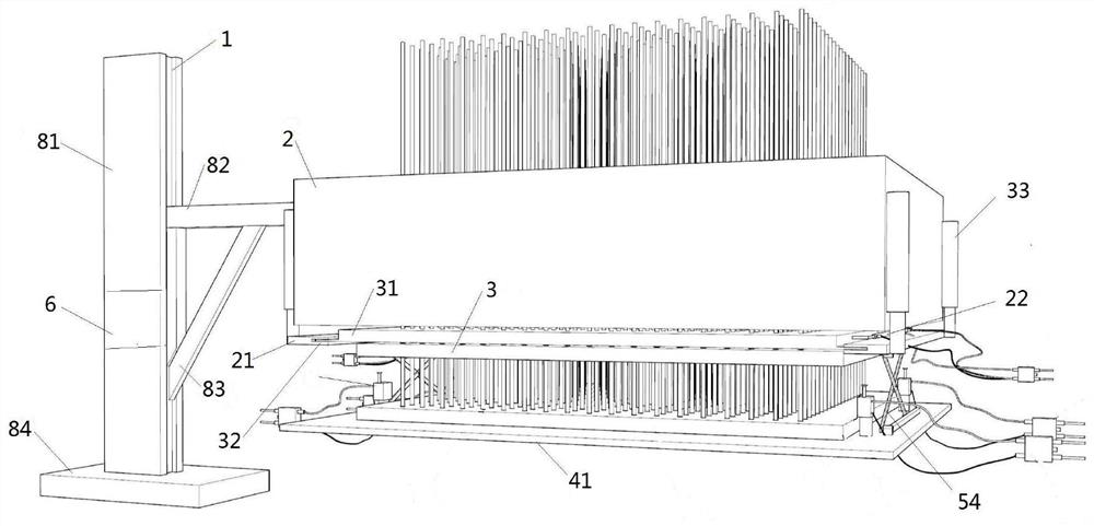
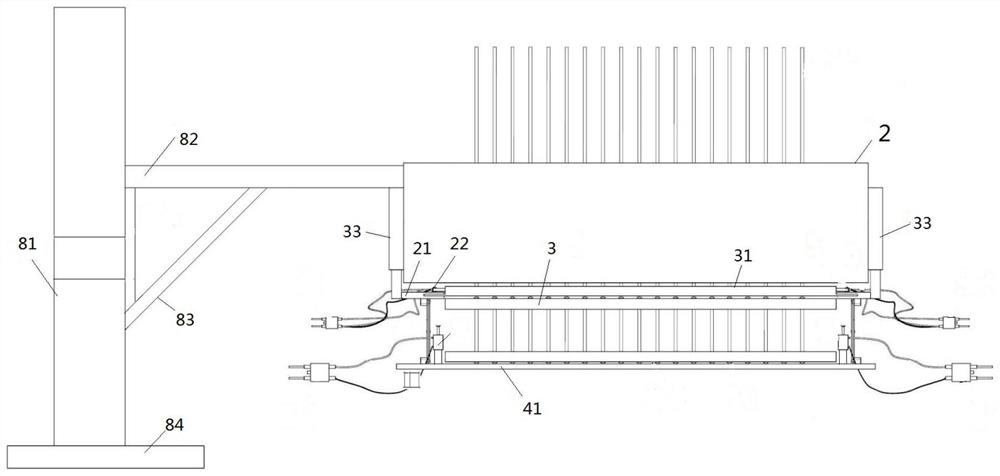
[0040] Such as Figure 1-2 Shown, a kind of light-transmitting cement-based material preparation device comprises:

[0041] bracket 1;

[0042] The placement frame 2 is vertically arranged on one side of the support 1 and suspended in the air, and the placement frame 2 is connected to the support 1;

[0043] The pay-off assembly is arranged directly above the placing frame 2, and is used to realize fixing the optical fiber;

[0044] A plurality of frame plates 3 are horizontally stacked inside the placement frame 2;

[0045] The fixing component is arranged inside the placement frame 2 and is used to fix the frame plate 3;

[0046] The cutting assembly is arranged under the placing frame 2, and is used to cut the optical fiber along the horizontal direction;

[0047] The guide assembly is arranged below the cutting assembly and is used to guide the frame plate 3 to move downward;

[0048] The controller 6 is arranged on the bracket 1, and the controller 6 is electrically ...

Embodiment 2

[0051] A method for using a light-transmitting cement-based material preparation device, comprising the following steps:

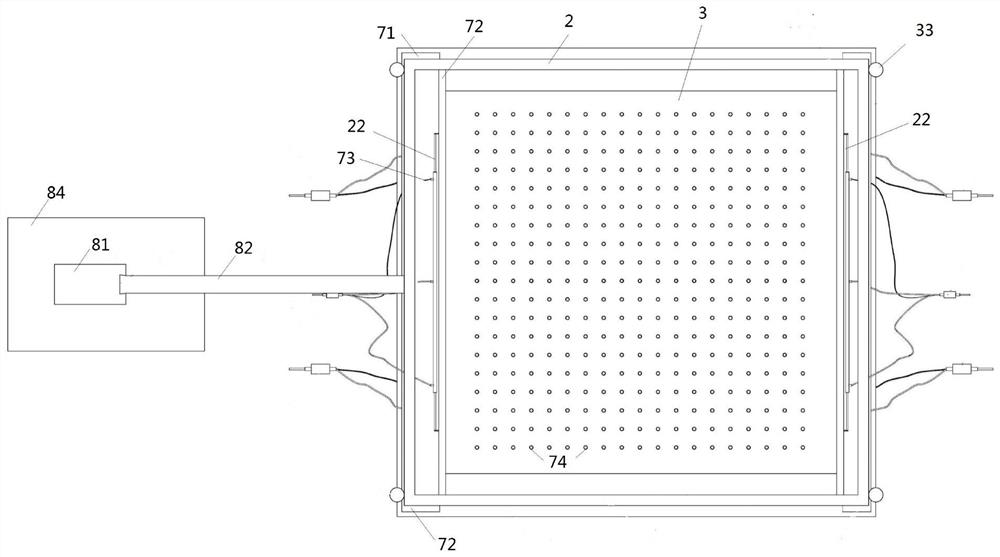
[0052] S1, stack the frame plate 3 horizontally inside the placement frame 2, and fix it by the splint 72, and then pass the optical fiber through the through hole 74 and extend out of the first frame plate at the bottom;

[0053] S2, after opening the electric heating riveting plate 31 to reach a predetermined temperature, start the electric heating riveting plate 31 to cut the optical fiber along the lower side of the first frame plate and form a riveting head to fix it;

[0054] S3, moving the first frame plate downward to the bottom plate 41 by pulling the manipulator;

[0055] S4, the second frame plate is pulled by the manipulator and moved down to the bottom of the electric heating riveting plate 31, and the optical fiber is cut along the upper side of the second frame plate through the electric heating riveting plate 31 and fixed with a riveting he...

Embodiment 3

[0059] In order to further improve the smoothness and rapidity of optical fiber cutting, a bidirectional cylinder is set to drive the cutter to slide for cutting;

[0060] Preferably, the cutting assembly includes two cutters, and the two cutters are symmetrically arranged on both sides of the bottom of the placement frame 2 respectively, and two guide plates 21 are respectively provided at both ends of the cutter, and the two ends of the cutter are respectively connected to The guide plate 21 is slidably connected, and a two-way cylinder 22 is fixed in the middle of the top of the guide plate 21. The output ends of the two-way cylinder 22 are respectively connected to the cutters on both sides, the guide plate 21 is connected to the placement frame 2, and the two-way cylinder 22 is connected to the controller 6 electrical connection.

[0061] When the optical fiber needs to be cut, the two-way cylinder is controlled by the control panel to drive the cutter to slide relatively...


PUM


Abstract

The invention relates to a preparation device for a light-transmitting cement-based material and a using method thereof, and belongs to the technical field of production equipment for light-transmitting cement-based materials. The preparation device comprises a support, a placing frame, a paying-off assembly, a plurality of frame plates, a fixing assembly and a cutting assembly, wherein the placing frame is vertically arranged on one side of the support and is suspended, and the placing frame is connected with the support; the paying-off assembly is arranged right above the placing frame and is used for fixing optical fibers; the plurality of frame plates are horizontally stacked in the placing frame; the fixing assembly is arranged in the placing frame and is used for fixing the frame plates; and the cutting assembly is arranged below the placing frame and is used for cutting off the optical fibers in the horizontal direction. According to the preparation device, the standard of frame construction is guaranteed through the gravity of the frame plates and the optical fibers, and electric heating rivet plates can cut the optical fibers and can also enable the optical fibers and the frame plates to form connecting anchor points, so that the displacement of the optical fibers in the pouring process is prevented, and the quality of the prepared light-transmitting cement-based material is improved; and the preparation device is simple to operate, convenient to use, high in practicability and worthy of popularization.

Description

technical field [0001] The invention belongs to the technical field of production equipment for light-transmitting cement-based materials, and in particular relates to a preparation device for light-transmitting cement-based materials and a method for using the same. Background technique [0002] The light-transmitting cement-based material product is a process in which cement, sand aggregate, additives and other admixtures are used as mixed materials, mixed with a certain proportion of water to form a cement-based slurry, and then the cement-based slurry is poured into the mold. The optical fiber is pre-embedded in the cement-based slurry or implanted with the drilling method after the cement-based slurry is hardened, so that the cement-based product has a certain light-transmitting ability, and the optical fiber can also be arranged in the cement matrix according to the design pattern according to actual needs. Make the surface of cement-based material products transmit li...

Claims


Application Information

Patent Timeline
IPC IPC(8): B28B1/14B28B17/00B28B23/00
CPCB28B1/14B28B17/00B28B17/0036B28B17/0081B28B23/0037
Inventor 王玉林范玉容林秀琴连锦康陈强庄思雨
Owner 武夷学院
Why Eureka
Try Eureka