Sulfur-iron self-oxidation denitrification device and reaction control method

A technology of sulfur self-oxygen denitrification tank and denitrification, which is applied in chemical instruments and methods, anaerobic digestion treatment, biological treatment devices, etc. Good sealing, not easy to unload, reliable opening and closing

Active Publication Date: 2021-06-08
臻和慧联(浙江)环境科技有限公司
View PDF5 Cites 1 Cited by
  • Summary
  • Abstract
  • Description
  • Claims
  • Application Information

AI Technical Summary

Problems solved by technology

[0002] Sulfur-iron autotrophic denitrification technology is used in more and more applications in sewage treatment. The combination of the two can synergistically carry out deep denitrification of sewage. In the existing technology, the adequacy of the reaction needs to be verified and a reasonable ratio can be realized. At the same time, there is less involvement in the reaction control in the later stage of the reaction device that has been formed, and there is no precise control of the temperature and concentration changes in the reaction

Method used


Image

  • Sulfur-iron self-oxidation denitrification device and reaction control method
  • Sulfur-iron self-oxidation denitrification device and reaction control method

Examples


Embodiment 1

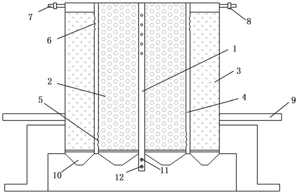
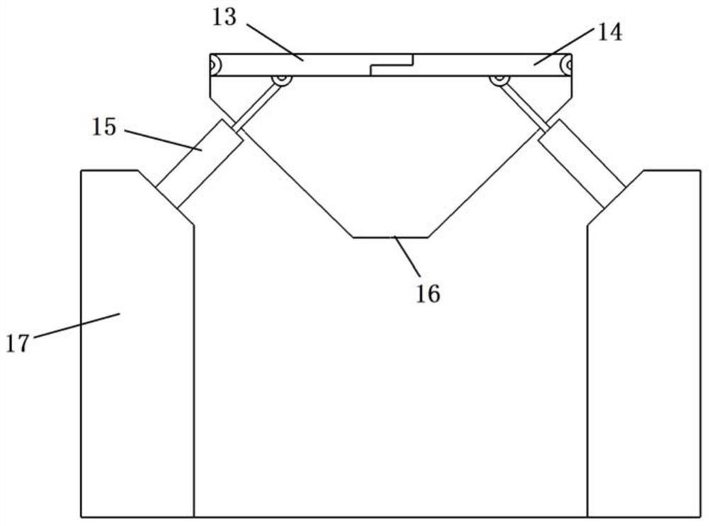
[0047] Figure 1 ~ Figure 2A specific embodiment of the present invention is shown, a sulfur iron aerobic denitrification device, comprising an iron aerobic denitrification bin 2 and a sulfur aerobic denitrification bin 3; the iron aerobic denitrification bin 2 is provided with a The water device is connected between the iron self-oxygen denitrification chamber 2 and the sulfur self-oxygen denitrification chamber 3; the top of the sulfur self-oxygen denitrification chamber 3 is provided with an air outlet pipe 7; the air outlet pipe 7 is provided with a gas concentration sensor , a gas flow sensor 8, a signal collector and a signal transmitter; the lower part of the sulfur auto-oxygen denitrification chamber 3 is provided with an outlet pipe 9; the signal transmitter transmits gas data information to the control platform.

[0048] The iron oxygen denitrification chamber and the sulfur oxygen denitrification chamber are independently designed, so that the reaction occurs indepe...

Embodiment 2

[0066] A method for controlling the reaction of a sulfur-iron autooxygen denitrification device, comprising the following steps:

[0067] 1) Pass sewage into the first hollow plate, and the sewage flows into the iron self-oxygen denitrification chamber through the first outlet hole on the upper part;

[0068] 2) The denitrified liquid and the reaction gas pass through the water inlet hole at the bottom to the second water outlet hole at the top and flow into the sulfur oxygen denitrification chamber;

[0069] 3) After the reaction of the sulfur self-oxygen denitrification chamber, the liquid is discharged through the outlet pipe, and the reaction gas is discharged through the exhaust pipe at the top;

[0070] 4) The control platform receives the gas flow and gas concentration data, judges according to the gas data, if the gas concentration is greater than or equal to the threshold, and the gas flow is lower than the threshold, it is judged that the pipeline is blocked and need...


PUM


Abstract

The invention discloses a sulfur-iron self-oxidation denitrification device and a reaction control method. The sulfur-iron self-oxidation denitrification device comprises an iron self-oxidation denitrification bin and a sulfur self-oxidation denitrification bin, a water inlet device is arranged in the iron self-oxidation denitrification bin, and the iron self-oxidation denitrification bin is communicated with the sulfur self-oxidation denitrification bin; a gas outlet pipe is arranged at the top of the sulfur self-oxidation denitrification bin; a gas concentration sensor, a gas flow sensor, a signal collector and a signal transmitter are arranged on the gas outlet pipe; a water outlet pipe is arranged at the middle lower part of the sulfur auto-oxidation denitrification bin; the signal transmitter transmits the gas data information to the control platform; and the invention further discloses the reaction control method. The nitration device disclosed by the invention is sufficient in reaction and good in reaction controllability.

Description

technical field [0001] The invention relates to the technical field of sewage biological treatment, in particular to a sulfur iron aerobic denitrification device and a reaction control method. Background technique [0002] Sulfur-iron autotrophic denitrification technology is used in more and more applications in sewage treatment. The combination of the two can synergistically carry out deep denitrification of sewage. In the existing technology, the adequacy of the reaction needs to be verified and a reasonable ratio can be realized. At the same time, there is less involvement in the reaction control in the later stage of the reaction device that has been formed, and there is no precise control of the temperature and concentration changes in the reaction. Contents of the invention [0003] The technical problem to be solved by the present invention is to provide a kind of sulfur iron aerobic denitrification device and reaction control method in view of the deficiencies in ...

Claims


Application Information

Patent Timeline
Patent Type & Authority Applications(China)
IPC IPC(8): C02F3/28C02F3/34C02F3/00
CPCC02F3/2866C02F3/34C02F3/00C02F2203/006C02F2209/38C02F2209/06C02F2209/02
Inventor 韩彦涛陈力辉
Owner 臻和慧联(浙江)环境科技有限公司
Why Eureka
Try Eureka