Compressed air energy storage system and method

A technology of compressed air energy storage and air, applied in the field of energy storage, can solve the problems of throttling loss and unstable inlet pressure of the expander.

Pending Publication Date: 2021-06-08
TSINGHUA UNIV +2
View PDF0 Cites 9 Cited by
  • Summary
  • Abstract
  • Description
  • Claims
  • Application Information

AI Technical Summary

Problems solved by technology

[0004] The present invention provides a compressed air energy storage system and method, which can solve the problem

Method used


Image

  • Compressed air energy storage system and method

Examples


Embodiment 1

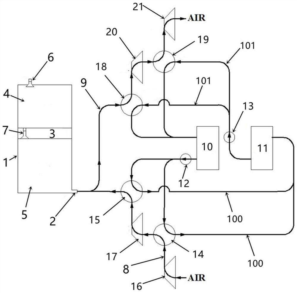
[0050] Combine below figure 1 Describe a compressed air energy storage system of the present invention, a compressed air energy storage system, including an air chamber 1 and an air charging and discharging nozzle 2, and a piston 3 that can move up and down is installed in the air chamber 1, and the piston 3 and the air chamber 1. The inner walls are sealed and lubricated well, and can move up and down freely. The piston 3 separates the air chamber 1 into the upper low-pressure chamber 4 and the lower high-pressure chamber 5. When the piston 3 moves up and down, the volume of the high-pressure chamber 5 and the low-pressure chamber 4 The low-pressure chamber 4 is provided with a low-pressure communication port 6 that can be connected to the outside world. When the low-pressure communication port 6 is opened, the low-pressure chamber 4 communicates with the external environment and the pressure is balanced. Connect the high-pressure communication port 7 of the low-pressure cham...

Embodiment 2

[0078] This embodiment is similar to Embodiment 1, the difference is that the inflation method in the operation method is different, as follows:

[0079] S1, using a braking mechanism to control the piston 3 to be stationary;

[0080] S2, open the high-pressure communication port 7, connect the low-pressure chamber 4 to the high-pressure chamber 5, balance the pressure in the high-pressure chamber 5 and the low-pressure chamber 4, and balance the pressure P2

[0081] S3, open the inflation and discharge nozzle 2 and the air compression pipeline 8, start the first-stage compressor 16 and the second-stage compressor 17, and ignore the resistance loss along the way, the initial back pressure of the second-stage compressor 17 is P2, here The power consumption of the air compressor unit is W2;

[0082] The outside air is continuously compressed by the first-stage compressor 16 and the second-stage compressor 17 during the process of entering the high-pressure chamber 5 from th...

Embodiment 3

[0088] This embodiment is similar to Embodiment 1, the difference is that the inflation method in the operation method is different, as follows:

[0089] When inflation is required, the following steps are included:

[0090] S1, open the low-pressure communication port 6, the inflation and deflation pipe port 2 and the air compression pipeline 8, so that the pressure in the high-pressure chamber 5 and the low-pressure chamber 4 is balanced, and the balance pressure P2

[0091] S2, start the first-stage compressor 16 and the second-stage compressor 17, and the external air is continuously compressed by the first-stage compressor 16 and the second-stage compressor 17 after entering the high-pressure chamber 5 from the air compression pipeline 8, so as to Make the air pressure in the high-pressure chamber 5 continue to rise and push the piston 3 to move upward, and the initial back pressure of the secondary compressor 17 is P2;

[0092] S3, while performing step S2, open the...


PUM


Abstract

The invention relates to the technical field of energy storage, in particular to a compressed air energy storage system and method.The compressed air energy storage system comprises an air cavity and an inflation and deflation pipe orifice, a piston capable of moving up and down is arranged in the air cavity and divides the air cavity into an upper low-pressure cavity and a lower high-pressure cavity, and the low-pressure cavity is provided with a low-pressure communication opening capable of communicating with the outside. The piston is provided with a high-pressure communicating opening capable of communicating the low-pressure cavity with the high-pressure cavity, the inflation and deflation pipe orifice communicates with the bottom of the high-pressure cavity, and the inflation and deflation pipe orifice is externally connected with a cooling compression device used for inflation and a heating expansion device used for deflation. According to the compressed air energy storage system and method, the problems that in the compressed air energy storage system, the air inlet pressure of the expansion machine is unstable, and throttling losses exist can be solved.

Description

technical field [0001] The invention relates to the technical field of energy storage, in particular to a compressed air energy storage system and method. Background technique [0002] Energy storage, especially electric energy storage, is of great significance to the optimization of energy structure and the regulation of power grid operation. Compressed air energy storage system is a new energy storage technology. In 1978, Germany built the world's first demonstration compressed air energy storage power station, followed by the United States, Japan and Israel. The working principle of the compressed air energy storage power generation system is similar to that of pumped water storage. When the electricity consumption of the power system is at a low point, the system stores energy and utilizes the surplus electricity in the system. The compressor drives the air compressor to compress the air and convert the energy to The form of compressed air is stored in the gas storage ...

Claims


Application Information

Patent Timeline
IPC IPC(8): F04B41/02F01K7/02F28D20/00
CPCF01K7/02F04B41/02F28D20/0034Y02E60/14Y02E60/16
Inventor 文军梅生伟张学林薛小代张通裴杰卢吉曹学兴迟福东王超卢强
Owner TSINGHUA UNIV
Why Eureka
Try Eureka