Precise drive brushless motor and driver circuit

A driver circuit, brushless motor technology, applied in the direction of motor, electronic commutator, electronic commutation motor control, etc., can solve problems such as performance deterioration, and achieve the effect of increasing power, increasing torque, and saving electric energy

Pending Publication Date: 2021-06-08
彭明 +1
View PDF0 Cites 0 Cited by
  • Summary
  • Abstract
  • Description
  • Claims
  • Application Information

AI Technical Summary

Problems solved by technology

At the same time, the traditional method of changing the modulation pulse width to realize the change of the speed causes the torque of the motor to decrease due to the lack of energy supplied when the brushless motor is at a low speed, and the performance at low speeds deteriorates.

Method used


Image

  • Precise drive brushless motor and driver circuit
  • Precise drive brushless motor and driver circuit
  • Precise drive brushless motor and driver circuit

Examples


Embodiment Construction

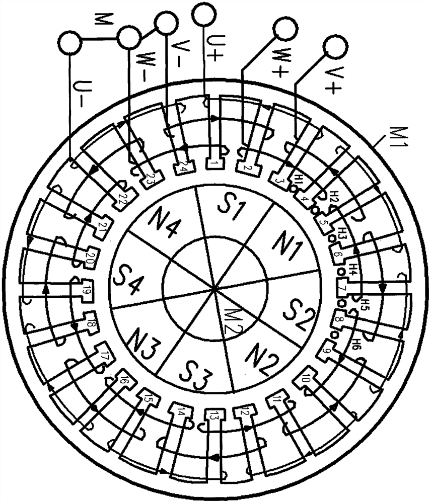
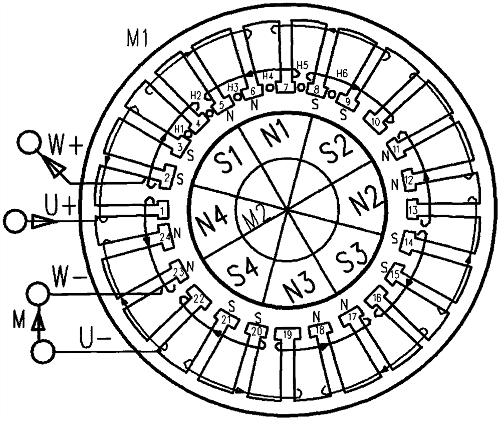
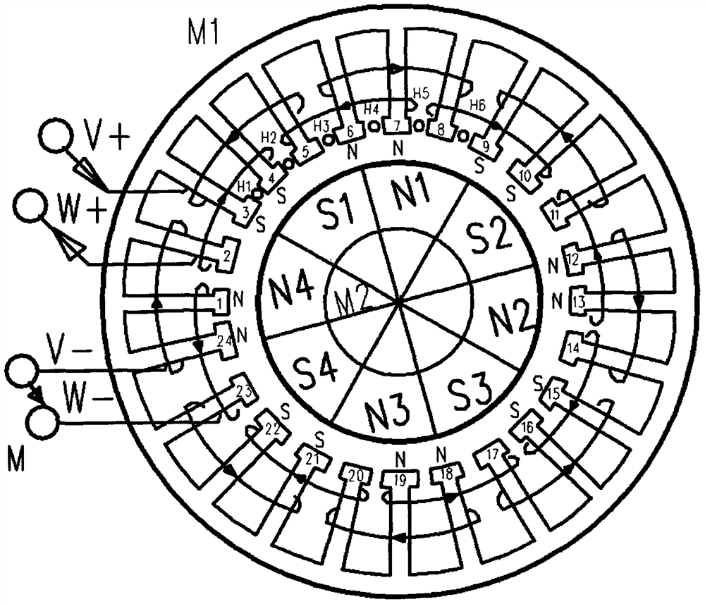
[0015] The invention provides precise drive brushless motor and its drive circuit, based on the principle of magnetic opposites attracting each other and same sex repelling each other, the position sensor is located in front of the driving coil in the brushless motor in the attraction rotation mode, after the position sensor gives a signal The driver energizes the phase coil in front of the position sensor to generate magnetic force to attract the rotor to the position of the phase coil, and then to the position of the next phase coil, thereby driving the rotor to rotate. In the repulsive force rotation mode, the position sensor is located behind the driving coil in the brushless motor. After the position sensor gives a signal, the driver energizes the phase coil behind the position sensor to generate magnetic force to repel the rotor to move away from the position of the phase coil. Then go to the coil position of the next phase, thereby driving the rotor to rotate. Drive the...


PUM


Abstract

The invention provides a precise drive brushless motor and a driver circuit. Different from a traditional brushless motor which usually adopts position sensors with the same number as the phase number, the precise driving brushless motor and the driver circuit provided by the invention adopt position sensors with the same number as the driving state to accurately sense the magnetic pole position of the rotor so as to realize precise driving. The stator coil of the brushless motor adopts star-shaped connection, and a winding winding mode mainly adopts the fact that a coil of a winding of the same phase is wound between two adjacent tooth grooves of a single armature tooth, so that a rotor rotates the position of the single armature tooth when being driven in each state, then the rotor is driven in the next state, and the rotor is driven to rotate in a driving mode of electrifying the two-phase coil state by state, so that the driving efficiency of electric energy is improved. Different from the traditional mode of changing the duty ratio to adjust the rotating speed in pulse width modulation, the mode of separating rotating speed adjustment and pulse width modulation is adopted, the fixed pulse width with the high duty ratio is adopted, and the rotating speed is adjusted in the mode of changing the rotating speed pulse frequency, so the motor has the characteristics that the rotating speed is in a large range, the large torque is kept, and meanwhile high electric energy driving efficiency is achieved. The precise drive brushless motor and the driver circuit also can be used for a motor wound across the tooth space, and can be widely applied to new-energy electric vehicles.

Description

[0001] The invention discloses precise driving of a brushless motor and a driver circuit, including the brushless motor and the driver circuit of the brushless motor. technical field [0002] The invention relates to the technical field of brushless motors and brushless motor driver circuits. Background technique: [0003] The brushless motor consists of a motor body and a drive circuit, and is a typical mechatronic product. [0004] Brushless motors are widely used in new energy electric vehicles, and its power directly affects the driving capability of electric vehicles. How to increase the power of brushless motors has also become an important factor. Improving the utilization rate of winding coils is an effective way to increase the power of brushless motors. At the same time, in the traditional way of changing the modulation pulse width to realize the change of the speed, when the brushless motor is at a low speed, the motor torque decreases due to the low energy suppl...

Claims


Application Information

Patent Timeline
IPC IPC(8): H02K3/28H02K1/27H02K29/08H02P6/08H02P6/14
CPCH02K3/28H02K1/27H02K29/08H02P6/085H02P6/14Y02T10/64
Inventor 彭明彭宇科
Owner 彭明
Why Eureka
Try Eureka