Building material cutting device for building engineering

A technology for building materials and construction engineering, applied in shearing devices, accessories of shearing machines, manufacturing tools, etc., can solve the problems of cutting edge damage, fixed device not having a buffer function, damage to raw materials, etc., to protect the cutting edge, Increases functionality and utility, reduces damage

Inactive Publication Date: 2021-06-11
广州杰明建材贸易有限公司
View PDF0 Cites 1 Cited by
  • Summary
  • Abstract
  • Description
  • Claims
  • Application Information

AI Technical Summary

Problems solved by technology

[0002] Construction engineering refers to the engineering entity formed through the construction of various types of housing construction machine ancillary facilities and the installation activities of its supporting lines, pipelines, and equipment. Therefore, some raw materials need to be cut into the required special shape during construction. and its size, but the existing construction shearing device will waste a lot of time when fixing the device, and cannot be automatically fixed, and when fixing, the fixing device does not have a buffer function, which may make the clip The holding device destroys the raw materials being held, resulting in waste of raw materials, and the cutting device can only move straight up and down, and cannot move up, down, left, and right according to the requirements. When the cutting device touches the raw material, the raw material will be cut. The blade produces a kind of thrust, so long-term cutting will damage the cutting edge, resulting in damage to the cutting device and increasing the cost of investment

Method used


Image

  • Building material cutting device for building engineering
  • Building material cutting device for building engineering
  • Building material cutting device for building engineering

Examples


Embodiment Construction

[0020] The following will clearly and completely describe the technical solutions in the embodiments of the present invention with reference to the accompanying drawings in the embodiments of the present invention. Obviously, the described embodiments are only some, not all, embodiments of the present invention. Based on the embodiments of the present invention, all other embodiments obtained by persons of ordinary skill in the art without making creative efforts belong to the protection scope of the present invention.

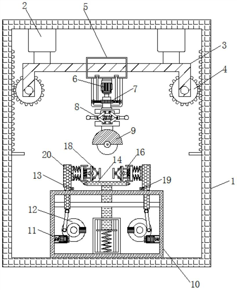
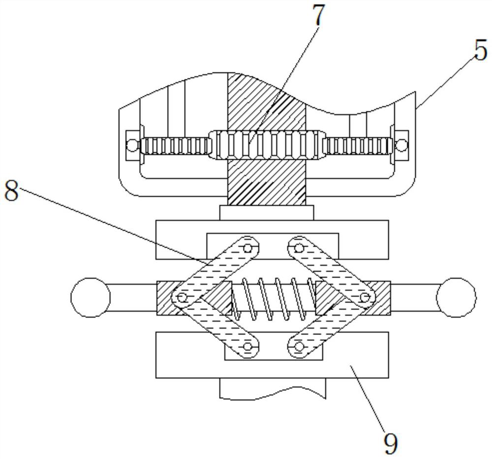
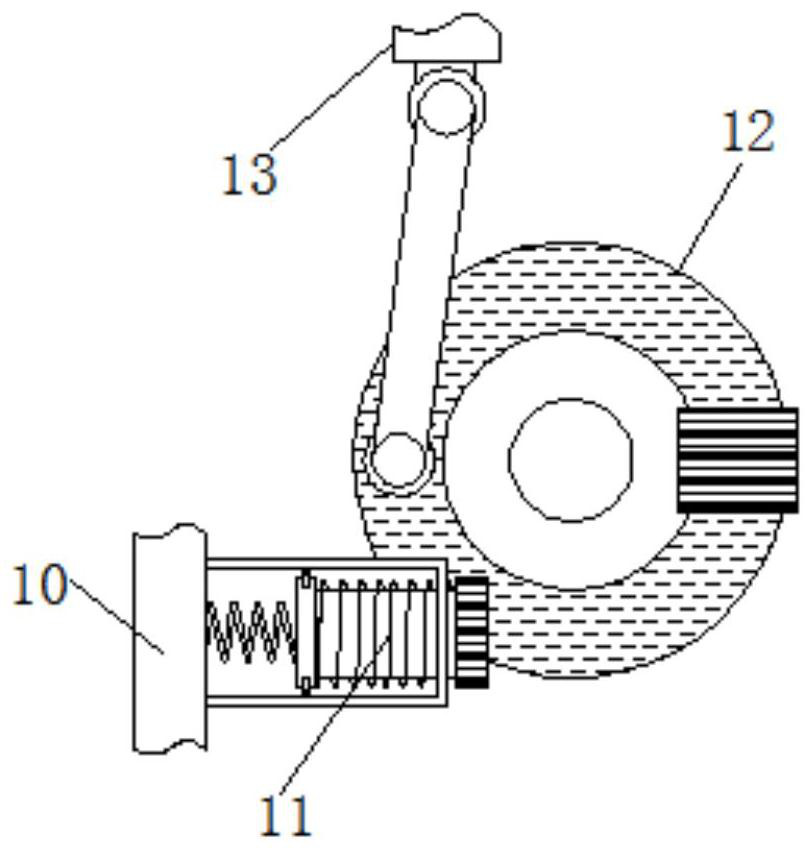
[0021] see Figure 1-4 , a building material cutting device for construction engineering, including a fuselage 1, tooth plates are fixedly connected to the inner walls of both sides of the fuselage 1, and the tooth plates mesh with the first gear 4, so that the beam 3 can move up and down, and the machine The top inner wall of the body 1 is fixedly connected with a hydraulic telescopic rod 2, the bottom end of the hydraulic telescopic rod 2 is fixedly connecte...


PUM


Abstract

The invention relates to the technical field of constructional engineering, and discloses a building material cutting device for building engineering. The building material cutting device comprises a machine body, wherein a hydraulic telescopic rod is fixedly connected to the inner wall of the top end of the machine body, a cross beam is fixedly connected to the bottom end of the hydraulic telescopic rod, a first gear is rotatably connected to the bottom end of the cross beam, a sliding block is slidably connected to the surface of the cross beam, a motor is fixedly connected to the interior of the sliding block, a second gear is fixedly connected to the bottom end of the motor, a rotating rod is fixedly connected to the bottom end of the second gear, and a cutting blade is fixedly connected to the bottom end of the rotating rod. The automatic clamping device is formed by arranging a photoresistor, an illumination lamp, a magnet, a rotating disc, a triangular plate, a ball and a fixing frame, and has a telescopic buffering function, so that clamping of raw materials can be guaranteed, damage of clamping force to the raw materials can be reduced, and functionality and practicability of the device are improved.

Description

technical field [0001] The invention relates to the technical field of construction engineering, in particular to a construction material cutting device for construction engineering. Background technique [0002] Construction engineering refers to the engineering entity formed through the construction of various types of housing construction machine ancillary facilities and the installation activities of its supporting lines, pipelines, and equipment. Therefore, some raw materials need to be cut into the required special shape during construction. and its size, but the existing construction shearing device will waste a lot of time when fixing the device, and cannot be automatically fixed, and when fixing, the fixing device does not have a buffer function, which may make the clip The holding device destroys the raw materials being held, resulting in waste of raw materials, and the cutting device can only move straight up and down, and cannot move up, down, left, and right acc...

Claims


Application Information

Patent Timeline
Patent Type & Authority Applications(China)
IPC IPC(8): B23D19/00B23D33/02B23Q11/00
CPCB23D19/00B23D33/02B23Q11/0032
Inventor 周健容
Owner 广州杰明建材贸易有限公司
Why Eureka
Try Eureka