
Machine tool chip removal and cleaning device for numerical control machine tool

A technology of CNC machine tools and cleaning devices, which is applied to metal processing machinery parts, maintenance and safety accessories, metal processing equipment, etc., can solve the problems of time-consuming, labor-intensive and low efficiency of machine tool debris, achieve convenient recycling and improve cleaning efficiency , the effect of reducing workload

Active Publication Date: 2021-06-11
CHONGQING IND POLYTECHNIC COLLEGE
View PDF20 Cites 6 Cited by
  • Summary
  • Abstract
  • Description
  • Claims
  • Application Information

AI Technical Summary

Problems solved by technology

[0004] The present invention intends to provide a machine chip removal and cleaning device for CNC machine tools to solve the problems of time-consuming, laborious and low efficiency of manual removal of machine tool chips

Method used


Image

  • Machine tool chip removal and cleaning device for numerical control machine tool
  • Machine tool chip removal and cleaning device for numerical control machine tool
  • Machine tool chip removal and cleaning device for numerical control machine tool

Examples


Embodiment 1

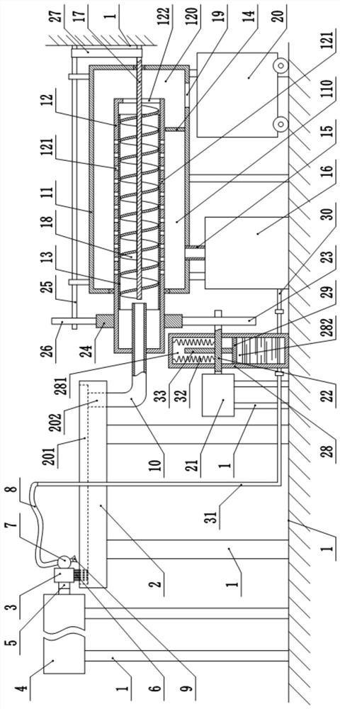
[0031] This embodiment is basically as figure 1 Shown: a machine chip cleaning device for CNC machine tools, including a frame 1, a recovery mechanism and a cleaning mechanism located above the CNC machine tool 2, the cleaning mechanism includes a moving plate 3 and a drive assembly for driving the moving plate 3 to move , in this embodiment, the driving assembly one includes a hydraulic cylinder 4 and a push rod 5, the hydraulic cylinder 4 is fixedly mounted on the frame 1 by bolts, the output end of the hydraulic cylinder 4 is fixedly connected with the push rod 5 by bolts, and the push rod 5 The right end is welded with the mobile plate 3.

[0032] The bottom surface of the moving plate 3 is bonded with a cleaning brush 6 corresponding to the groove 201 on the CNC machine tool 2, and the right side wall of the moving plate 3 is welded with a flushing pipe 7, which is connected with a liquid inlet hose 8 and several Nozzle 9, in this embodiment, each groove 201 corresponds ...

Embodiment 2

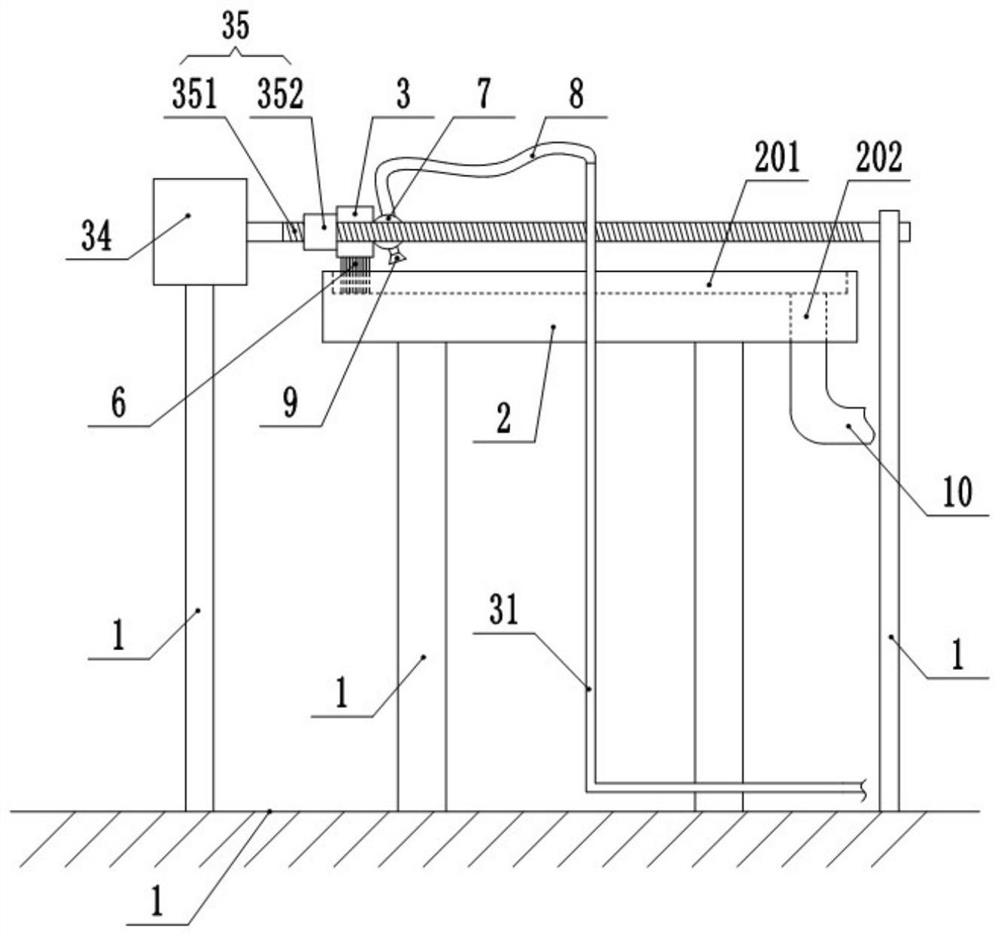
[0044] The difference between this embodiment and Embodiment 1 is that: figure 2 As shown, the drive assembly one includes two motors one 34 and two ball screw pairs 35 ( figure 2 Among them, two motors 34 and two ball screw pairs 35 are all arranged front and rear, therefore, only one motor 34 and a pair of ball screw pairs 35 can be seen), and the output end of motor 1 34 is located on the same side as The leading screw 351 of the ball screw pair 35 is connected, and the nut 352 of the ball screw pair 35 is welded with the moving plate 3 . Motor one 34 and motor two 21 ( figure 1 Middle) in series in the same electrical circuit.

[0045] In this embodiment, since the first motor 34 and the second motor 21 are connected in series in the same electrical circuit, the first motor 34 and the second motor 21 can be turned on and off at the same time, reducing the amount of work for workers. When motor one 34 starts, motor one 34 drives the leading screw 351 of ball screw pair...

Embodiment 3

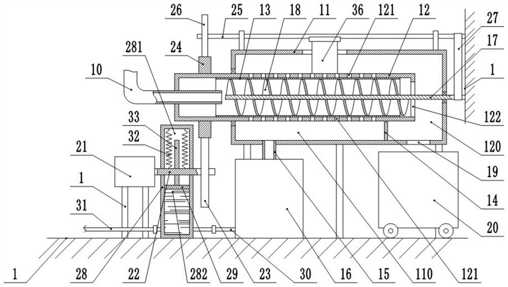
[0047] The difference between this embodiment and Embodiment 1 is that: image 3 As shown, the middle part of the third rotating shaft 25 is hinged with an impact plate 36 , specifically, in this embodiment, the impact plate 36 is hinged on the third rotating shaft 25 through a hinge. The outer surface of the impact plate 36 is bonded with a rubber layer, and the top of the cylinder 11 is provided with an arc-shaped groove for the impact plate 36 to rotate.

[0048] In this embodiment, during the clockwise rotation of the rotating shaft 3 25, the impact plate 36 is driven to rotate, and the impact plate 36 can intermittently impact the drum 12, so that the drum 12 and the circular filter screen 13 in the drum 12 vibrate, thereby The debris stuck on the circular filter screen 13 is shaken off to prevent the debris from clogging the circular filter screen 13 .


PUM


Abstract

The invention relates to the field of numerical control machine tools, and discloses a machine tool chip removal and cleaning device for a numerical control machine tool. The machine tool chip removal and cleaning device comprises a rack, a cleaning mechanism and a recycling mechanism, the cleaning mechanism comprises a moving plate and a driving assembly I, the bottom surface of the moving plate is provided with a cleaning brush, the side wall of the moving plate is provided with a flushing pipe, and the flushing pipe is communicated with a liquid inlet hose and a plurality of nozzles; a chip removal channel is arranged on the numerical control machine tool, the top end of the chip removal channel is communicated with each groove on the numerical control machine tool, and the bottom end of the chip removal channel is communicated with a chip removal pipe; the recycling mechanism comprises a cylinder which is horizontally arranged and fixedly connected to the rack; a rotating cylinder is coaxially and rotatably connected to the interior of the cylinder; the chip removal pipe extends into the rotating cylinder, and the chip removal pipe and the rotating cylinder are coaxial; a circular filter screen is arranged on the inner circumferential wall of the rotating cylinder; a plurality of liquid leakage holes are arranged on the circumferential wall of the rotating cylinder; and the liquid leakage holes are all located in the cylinder. According to the machine tool chip removal and cleaning device for the numerical control machine tool provided by the invention, chips can be automatically cleaned, cleaning liquid and the chips can be recycled separately, the workload of workers is reduced, and the chip cleaning efficiency is improved.

Description

technical field [0001] The invention relates to the field of numerically controlled machine tools, in particular to a machine chip removal and cleaning device for numerically controlled machine tools. Background technique [0002] CNC machine tool is the abbreviation of numerical control machine tool, which is an automatic machine tool equipped with a program control system. The control system on the CNC machine tool can logically process the program specified by the control code or other symbolic instructions, and decode it, express it in coded numbers, input it into the CNC device through the information carrier, and send out various commands from the CNC device after calculation and processing. Control the signal, control the movement of the machine tool, and automatically process the parts according to the shape and size required by the drawing. CNC machine tools solve complex, precise, small-batch, and multi-variety parts processing problems. It is a flexible and high-...

Claims


Application Information

Patent Timeline
Patent Type & Authority Applications(China)
IPC IPC(8): B23Q11/00
CPCB23Q11/0042
Inventor 游晓畅
Owner CHONGQING IND POLYTECHNIC COLLEGE
Learn More