Jet spray type cooling tower device with high energy-saving effect
An energy-saving and cooling tower technology, applied in the field of cooling towers, can solve the problems of insufficient water source, troublesome replacement and cleaning, and reduced work efficiency, and achieve the effects of convenient light reception, easy disassembly and cleaning, and saving electricity costs.
- Summary
- Abstract
- Description
- Claims
- Application Information
AI Technical Summary
Problems solved by technology
Method used
Image

Examples
Embodiment 1
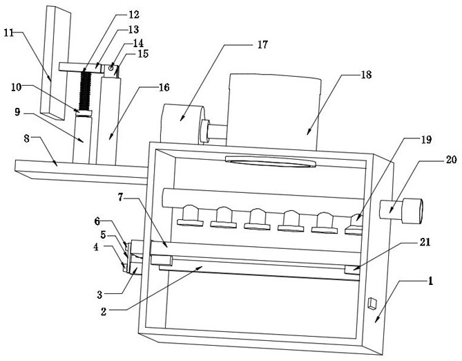
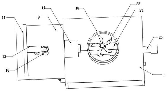
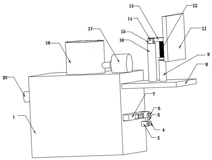
[0031] see Figure 1-7 , the present invention provides a technical solution: a jet spray type cooling tower device with high energy saving effect, comprising a cooling tower body 1, an evaporation jacket plate 18 is arranged on the top of the cooling tower body 1, and the inside of the evaporation jacket plate 18 is fixedly installed There is a clamping plate 23, the interior of the clamping plate 23 is rotatably connected with a rotating shaft rod 29, the bottom of the rotating shaft rod 29 is fixedly installed with a first bevel gear 30, the top of the cooling tower body 1 is fixedly installed with a motor 17, and the output of the motor 17 is fixed. The second bevel gear 31 is fixedly installed at the output end of the motor 17, the teeth of the second bevel gear 31 are meshed with the teeth of the first bevel gear 30, and the top of the rotating shaft rod 29 is fixed A fixing rod is installed, the outer part of the fixing rod is fixedly sleeved with a sleeve 24, the inner...
Embodiment 2
[0034] see Figure 1-7As shown, on the basis of Embodiment 1, the present invention provides a technical solution: a water pipe 20 is fixedly installed inside the cooling tower body 1, and six correspondingly distributed nozzles 19 are fixedly installed at the bottom of the water pipe 20. The cooling tower body The inside of 1 is fixedly installed with the slider 2, the inside of the cooling tower body 1 is provided with a filter plate 7, the bottom of the filter plate 7 is provided with a groove, the filter plate 7 is slidably connected with the slider 2 through the groove, and the outside of the filter plate 7 is fixed and installed There are two correspondingly distributed connection blocks 34, a tension band 35 is fixedly installed between the two connection blocks 34, a fixing plate 8 is fixedly installed on the outside of the cooling tower body 1, and a retention column 16 is fixedly installed on the top of the fixing plate 8 , the top of the retaining column 16 is fixed...
Embodiment 3
[0037] see Figure 1-7 As shown, on the basis of Embodiment 1 and Embodiment 2, the present invention provides a technical solution: the outside of the rotating shaft rod 29 is fixedly installed with two correspondingly distributed card slot blocks 28, and the outside of the sleeve 24 is fixedly installed with Two correspondingly distributed clamping rods 26, the bottoms of the two clamping rods 26 are fixedly installed with clamping rods 27, the clamping rods 27 are clamped inside the clamping slot block 28, and the interior of the cooling tower body 1 is fixedly installed There are two correspondingly distributed limit blocks 21, the limit blocks 21 are located at the bottom of the filter plate 7, the filter plate 7 is fixedly installed with a filter screen 36, the filter screen 36 is made of activated carbon material, and the outside of the filter plate 7 is fixedly installed There is a rotating rod 6, the outside of the rotating rod 6 is rotatably connected with a rotating...
PUM
 Abstract
Description
Claims
Application Information
PatSnap Eureka turns technology decisions into work you can execute. Powered by our Innovation Knowledge Graph, it runs expert workflows across engineering, life sciences, materials and intellectual property. Get your review-ready output in minutes.


