Cobalt-rich crusting thickness measuring method based on multi-beam receiving technology

A cobalt-rich crust and measurement method technology, applied in the field of geological exploration, can solve problems such as measurement errors, and achieve the effects of high efficiency, high thickness measurement accuracy, and large measurement area

Active Publication Date: 2021-06-11
NAT DEEP SEA CENT
View PDF13 Cites 0 Cited by
  • Summary
  • Abstract
  • Description
  • Claims
  • Application Information

AI Technical Summary

Problems solved by technology

If the signal incident grazing angle is simply approximated as 90° (incident grazing angle: the angle between the signal incident direction and the horizontal direction), it will inevitably lead to certain measurement errors

Method used


Image

  • Cobalt-rich crusting thickness measuring method based on multi-beam receiving technology
  • Cobalt-rich crusting thickness measuring method based on multi-beam receiving technology
  • Cobalt-rich crusting thickness measuring method based on multi-beam receiving technology

Examples


Embodiment 1

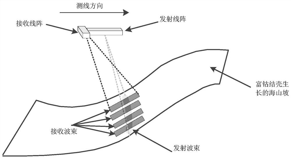
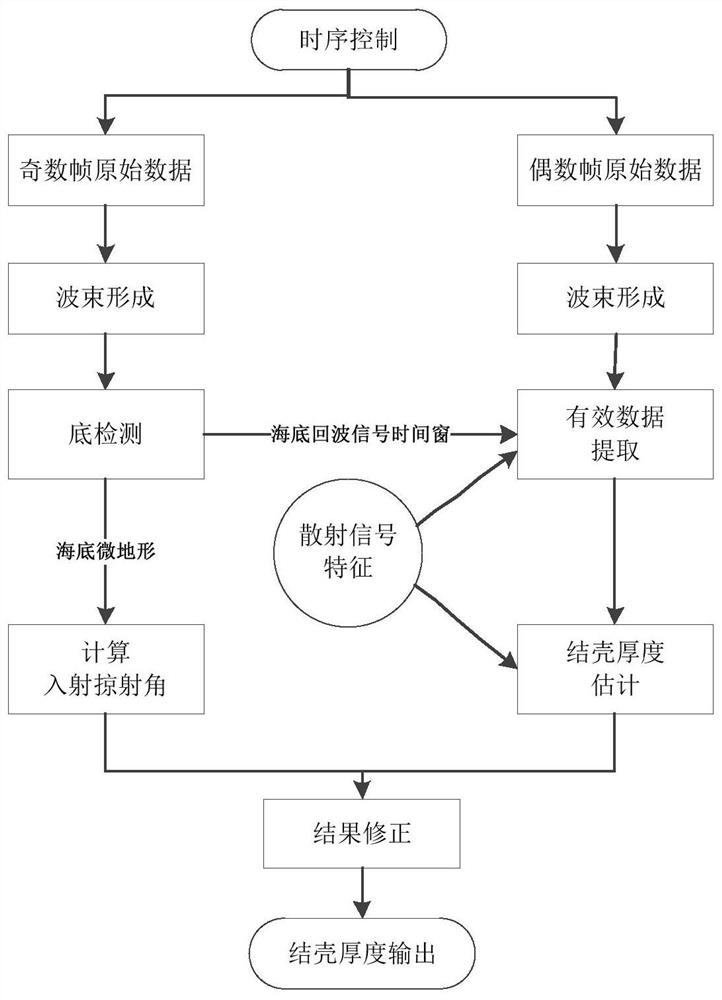
[0017] The method of the present invention utilizes the multi-beam receiving technology, and the transmitting line array and the receiving line array adopt a T-shaped arrangement, such as figure 1 As shown, the transmitting line array is parallel to the direction of the survey line (the heading of the submersible carrier on which the crust thickness measurement equipment is installed), and the receiving line array is perpendicular to the direction of the survey line. Data processing flow such as figure 2 As shown, the narrowband high-frequency PCW signal is first transmitted (here, the number of narrowband high-frequency signal transmissions is defined as an odd number of frames), and multiple receiving strips can be obtained by using the receiving beamforming technology, and then multiple The seabed echo signal at the measurement point and the backscattering signal at the interface between the seawater and the seabed are strong. The bottom detection algorithm is used to calc...

Embodiment 2

[0020] In this embodiment, the laboratory measurement and verification is carried out on the imitation crust sample mounted on the plate. The thickness of the imitation sample is 100mm, and the area is 500*500mm. Firstly, place the transmitting transducer at a height of 1100mm directly above the imitation sample, the transmitting beam of the transducer is in a 90° state with the imitation sample, the pulse width of the transmitting signal is 0.1ms, the center frequency is 100kHz, 100 consecutive transmissions, and the echo signal is received Finally, the method is used to calculate the thickness of the imitation sample, and the calculation results are statistically analyzed. The average value of the calculated thickness of the imitation sample is 98.8mm, and the variance is 1.4*10 -17. Adjust the angle of the imitation sample so that it is in the state of 80° with the beam emitted by the transducer, simulate the undulating and inclined state of the seabed, transmit the same s...


PUM


Abstract

The invention relates to a cobalt-rich crusting thickness measuring method based on a multi-beam receiving technology, and belongs to the technical field of geological prospecting. The method utilizes a multi-beam receiving technology, a transmitting linear array and a receiving linear array adopt a T-shaped arrangement mode, the transmitting linear array is parallel to the direction of a measuring line, and the receiving linear array is perpendicular to the direction of the measuring line. The direction of the measuring line is the course of a submersible carrier on which the crusting thickness measuring equipment is mounted; the crusting thickness values in a plurality of beams are primarily measured at a time by using a multi-beam measurement technology; and according to a multi-beam receiving technology, seabed micro-topographic relief is obtained, the incident angle of a signal in each beam is estimated, the crusting thickness obtained by measurement in each beam is further corrected, and the crusting thickness change is tracked by adopting a sequential inertial Bayesian filtering method in combination with the crusting thickness change characteristics so that the measurement precision is improved.

Description

technical field [0001] The invention belongs to the technical field of geological exploration, and in particular relates to a method for measuring the thickness of cobalt-rich crusts based on multi-beam receiving technology. Background technique [0002] Cobalt-rich crusts are rich in metals such as cobalt, nickel, platinum, and rare earths. Oxidized deposits of cobalt-rich crusts are found all over the world's oceans, concentrated on the slopes and tops of seamounts, ridges, and platforms. There are about 50,000 seamounts in the Pacific Ocean, which are rich in cobalt-rich crusts. Despite the abundance of cobalt-rich crusts on the ocean floor, few seamounts have been surveyed and sampled in detail. At present, the rough assessment of cobalt-rich crust resources mainly uses acoustic equipment such as shallow strata profilers, multi-beam bathymetric sonars, and side-scan sonars to obtain seabed echo signals, classify seabed bottoms and identify cobalt-rich crusts according t...

Claims


Application Information

Patent Timeline
Patent Type & Authority Applications(China)
IPC IPC(8): G01B15/02G01S15/02G01S7/539
CPCG01B15/02G01S15/02G01S7/539
Inventor 杨志国刘保华孙永福宗乐于凯本于盛齐史先鹏
Owner NAT DEEP SEA CENT
Why Eureka
Try Eureka