
Vacuum high-temperature reciprocating type frictional wear testing system

A friction and wear, reciprocating technology, applied in measuring devices, instruments, mechanical devices, etc., can solve the problems of hindering the research of lubricants and aviation materials, still need to be improved, expensive and other problems, and achieves low production cost, simple structure, Stable performance

Active Publication Date: 2021-06-11
QINGDAO UNIV OF SCI & TECH
View PDF16 Cites 1 Cited by
  • Summary
  • Abstract
  • Description
  • Claims
  • Application Information

AI Technical Summary

Problems solved by technology

The current vacuum high-temperature friction test equipment is complex in structure and expensive, which hinders the research of various properties of lubricants and aerospace materials under harsh working conditions by various small and medium-sized scientific research institutions.
In addition, the friction and wear performance test system of aerospace materials under various lubrication conditions in vacuum and high temperature environments still needs to be improved.

Method used


Image

  • Vacuum high-temperature reciprocating type frictional wear testing system
  • Vacuum high-temperature reciprocating type frictional wear testing system
  • Vacuum high-temperature reciprocating type frictional wear testing system

Examples


Embodiment 1

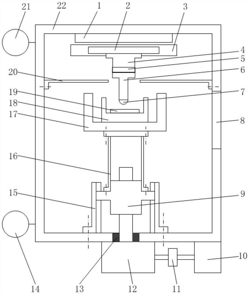
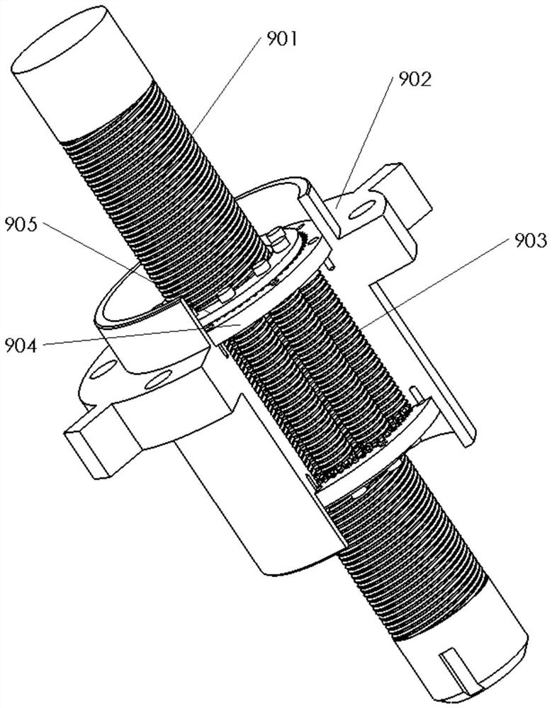
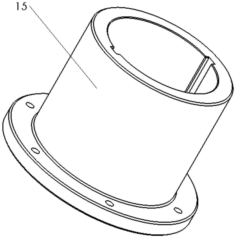
[0025] When the vacuum high-temperature reciprocating friction and wear testing system of the present invention is working, the linear motor mover 2 drives the connecting seat 4, the two-dimensional force sensor 5, the test ball mounting seat 6, and the test ball 7 to perform reciprocating linear motion, and the reciprocating frequency is passed by the linear motor Adjustment; the servo motor 10 provides the rotating power source for the screw 901 through the shaft coupling 11 and the reducer 12. When the guide base 15 is used to limit the rotational freedom of the ear nut 902, the screw 901 and the roller 903, the roller The cooperation between 903 and ear nut 902 converts the rotary motion of the screw rod 901 into the linear feed motion of the ear nut 902, thereby realizing the 902 linear feed movement.

[0026] The vacuum system 14 provides the vacuum environment required for the test; the induction heating furnace 17 provides the temperature from 25°C to 800°C; the data a...


PUM


Abstract

The invention discloses a vacuum high-temperature reciprocating type frictional wear tester, and belongs to the technical field of frictional wear detection. The system comprises a linear motor stator, a linear motor rotor, a linear guide rail, a connecting seat, a two-dimensional force sensor, a test ball mounting seat, a planetary roller screw, a servo motor, a speed reducer, a guide base, a squirrel cage bracket, an induction heating furnace, an oil box, a heat insulation plate, a vacuum box, a vacuum system, a data acquisition system and the like. The linear motor is connected with the upper surface in the vacuum box, and the linear guide rail supports and guides a rotor of the linear motor; the two-dimensional force sensor is mounted between the connecting seat and the sample ball mounting seat and is connected with the data acquisition system; the guide base is connected with the lower surface of the interior of the vacuum box to limit rotation of the lug-shaped nut, and linear movement of the lug-shaped nut is achieved through rotation of the lead screw; the ear-shaped nut is upwards connected with the squirrel cage bracket, the induction heating furnace, the oil box and the test disc in sequence; the heat insulation plate protects a stator and a rotor of the linear motor; and the vacuum system provides a vacuum environment required by a friction test. The system has the advantages that the tribological performance test of the material under the simulated working condition of the aerospace engine is realized, the tester is provided with the induction heating furnace, the linear feeding mechanism adopts the planetary roller screw, the test load is large, and the simulation temperature is high. In addition, the device has the advantages of simple structure, stable operation, low manufacturing cost and the like.

Description

technical field [0001] The invention relates to a vacuum high-temperature reciprocating friction and wear testing system, which belongs to the technical field of friction and wear detection. Background technique [0002] With the increasing demand for thrust, thrust-to-weight ratio and flight range of aero-engines, the working temperature, pressure and rotational speed of main shaft bearings have all increased significantly, and the working temperature of lubricating oil is as high as 350°C. The test of harsh working conditions such as high speed, heavy load and high temperature poses a great challenge to the reliability of lubrication of the friction surface of aviation hybrid bearings under all working conditions. The current vacuum high-temperature friction test equipment is complex in structure and expensive, which hinders the research of various properties of lubricants and aerospace materials under harsh working conditions by various small and medium-sized scientific r...

Claims


Application Information

Patent Timeline
Patent Type & Authority Applications(China)
IPC IPC(8): G01N19/02
CPCG01N19/02
Inventor 武路鹏解志杰赵海霞张永涛史伟杰
Owner QINGDAO UNIV OF SCI & TECH
Learn More