
Robot curved surface machining track optimization generation method, system and terminal

A curved surface processing and trajectory optimization technology, applied in general control systems, control/adjustment systems, instruments, etc., can solve the problems of work efficiency and curved surface processing quality, and achieve the effects of improving efficiency, high versatility, and ensuring quality

Inactive Publication Date: 2021-06-11
HEFEI UNIV OF TECH
View PDF7 Cites 6 Cited by
  • Summary
  • Abstract
  • Description
  • Claims
  • Application Information

AI Technical Summary

Problems solved by technology

[0006] Aiming at the problems in the prior art, the present invention provides a method, system and terminal for generating optimized curved surface processing trajectory of a robot, which solves the problem that work efficiency and curved surface processing quality cannot be balanced in the traditional method of curved surface processing path optimization.

Method used


Image

  • Robot curved surface machining track optimization generation method, system and terminal
  • Robot curved surface machining track optimization generation method, system and terminal
  • Robot curved surface machining track optimization generation method, system and terminal

Examples


Embodiment 1

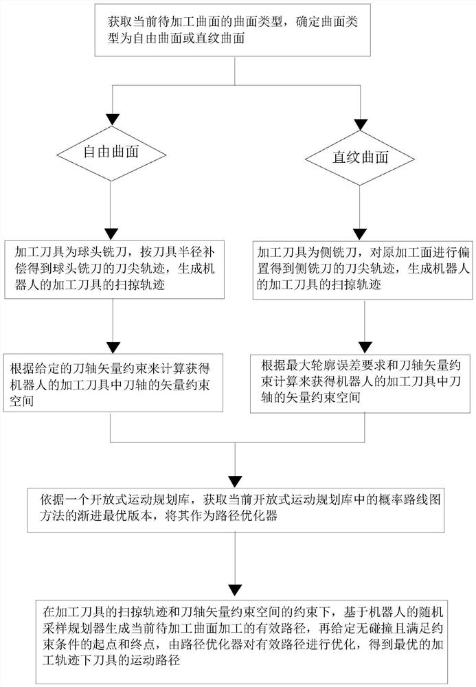
[0121] Such as figure 1 As shown, the present embodiment provides a method for optimizing and generating a robot curved surface processing trajectory, which is designed based on a random sampling algorithm and includes the following steps:

[0122] A method for optimizing and generating a robot curved surface machining trajectory, the method comprising the following steps:

[0123] S1: Obtain the surface type of the current surface to be processed, and determine whether the surface type is a free-form surface or a ruled surface;

[0124] S2: According to the surface type of the current surface to be processed, generate the sweep trajectory of the corresponding robot's processing tool, where:

[0125] (1) When the surface type to be processed is a free-form surface, the processing tool is a ball end milling cutter. At this time, the tool tip trajectory of the ball end milling cutter is obtained according to the tool radius compensation, and the sweeping trajectory of the robo...

Embodiment 2

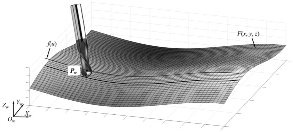
[0223] This embodiment is a kind of simulation experiment of the method that embodiment 1 provides, in this example, such as figure 2 As shown, the processed curved surface tested in this embodiment is a free curved surface.

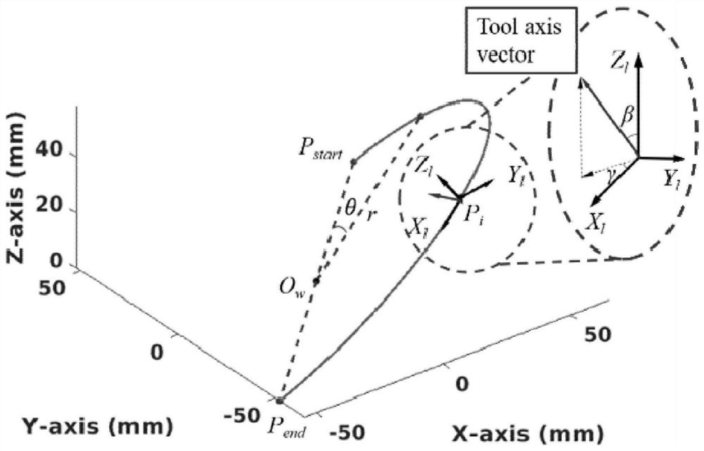
[0224] In this embodiment, an oblique semicircle tool path is used as the tool nose to follow and constrain the entire tool path, such as image 3 Shown, the circle radius r = 75mm. The parametric equation of the curve is:

[0225]

[0226] f(θ)=R z (θ z )*R x (θ x )*C(θ)

[0227] In the above formula, 0≤θ≤π, R z (θ z ) and R x (θ x ) is the rotation matrix around the Z and X axes, θ x = θ z =π / 4, f(θ) is the function of the tool path curve that the tool nose should follow.

[0228] The tool nose should strictly follow the tool nose trajectory curve, and the tool nose trajectory curve is:

[0229] P w =f(θ)

[0230] The position of the point on the tool in the workpiece space is:

[0231] P w =F(J)

[0232] In the above formula, P ...

Embodiment 3

[0265] This embodiment is a kind of simulation experiment of the method that embodiment 1 provides, in this example, such as Figure 10 As shown, the processed curved surface tested in this embodiment is a ruled curved surface.

[0266] In this embodiment, the tool trajectory curve of the side milling ruled surface of the elfin5 robot is planned with a sampling-based planner. Two directrix curves f expressed by third-order B-splines on the tool-swept surface 1 (u) and f 2 (u).

[0267] For a certain parameter u 0 , the tool axis movement curve is:

[0268] l(v)=f 1 (u 0 )+v*(f 2 (u 0 )-f 1 (u 0 ))

[0269] 0≤v≤1

[0270] The points on the surface are:

[0271] P(u 0 ,v 0 ) = f 1 (u 0 )+v 0 *(f 2 (u 0 )-f 1 (u 0 ))

[0272] The tool nose should follow the alignment curve, and the tool nose trajectory curve is:

[0273] P 1,w = f 1 (u)

[0274] In the above formula, P 1,w is the point of the tool axis in the workpiece space.

[0275] Therefore, the r...


PUM


Abstract

The invention belongs to the technical field of industrial robots, and particularly relates to a robot curved surface machining track optimization generation method, system and terminal. The method comprises the following steps: S1, obtaining the curved surface type of a current to-be-machined curved surface, and determining whether the curved surface type is a free-form curved surface or a straight-line curved surface; s2, generating a sweeping track of a machining tool of the corresponding robot; s3, calculating a vector constraint space of a cutter shaft of the robot; s4, obtaining a version with the optimal optimization performance in the probability route map method as a path optimizer; and S5, optimizing the effective path by a path optimizer under the constraint of the sweeping track of the machining tool and the tool axis vector constraint space to obtain an optimal machining track. The system comprises a curved surface type acquisition module, a sweeping trajectory generation module, a vector constraint space calculation module and a path planner module. According to the method, system and terminal, the problem that the working efficiency and the curved surface machining quality cannot be both considered in the curved surface machining path optimization process of a traditional method is solved.

Description

technical field [0001] The invention belongs to the technical field of industrial robots, and in particular relates to a method, a system and a terminal for optimally generating a robot curved surface processing trajectory. Background technique [0002] With the development of additive manufacturing and advanced molding manufacturing technology, the structure of parts has become more and more complex, the amount of material that needs to be removed during part processing is less and less, and the processing requirements for curved surfaces are getting higher and higher. These make it difficult for existing processing equipment and processing methods to meet the complex, high-quality and high-efficiency curved surface processing requirements in production practice. Due to the characteristics of good flexibility and low cost, robots are becoming more and more popular in the application of machining. In surface machining process, tool path optimization for surface machining is...

Claims


Application Information

Patent Timeline
IPC IPC(8): G05B19/19
CPCG05B19/19G05B2219/35349
Inventor 卢磊张恒韩江田晓青刘海军
Owner HEFEI UNIV OF TECH
Learn More