Treatment device for treating waste gas containing dichloroethane

A processing device, dichloroethane technology, applied in the direction of gas treatment, organic chemistry, transportation and packaging, etc., can solve the problem of low work efficiency, to achieve the effect of ensuring work efficiency and desorption effect

Pending Publication Date: 2021-06-15
江阴联众环保工程有限公司
View PDF6 Cites 0 Cited by
  • Summary
  • Abstract
  • Description
  • Claims
  • Application Information

AI Technical Summary

Problems solved by technology

[0004] In view of the above-mentioned related technologies, the inventor believes that after the adsorbent absorbs dichloroethane to a saturated state, it is necessary to suspen

Method used


Image

  • Treatment device for treating waste gas containing dichloroethane
  • Treatment device for treating waste gas containing dichloroethane
  • Treatment device for treating waste gas containing dichloroethane

Examples


Example Embodiment

[0041] Example 1

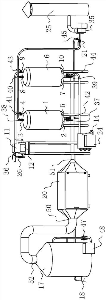
[0042] refer to figure 1 , the treatment device used to treat waste gas containing dichloroethane includes a washing tower 17, a dry filter 20, an adsorption tower 1, a second adsorption tower 6 and an exhaust tube 25, and the adsorption tower 1 and the second adsorption tower 6 pass through a pipeline A condenser 14 is connected. The outlet of the condenser 14 is connected with a recovery pool 24 . The washing tower 17 is provided with a washing inlet 18. After the waste gas enters through the washing inlet 18, it undergoes washing, filtering, adsorption and other operations, and finally enters the atmosphere from the exhaust pipe 25. The dichloroethane in the exhaust gas passes through the adsorption tower 1 and the second adsorption tower 6, and finally condenses into a liquid state through the condenser 14, and flows into the recovery pool 24, which is convenient for the staff to recycle.

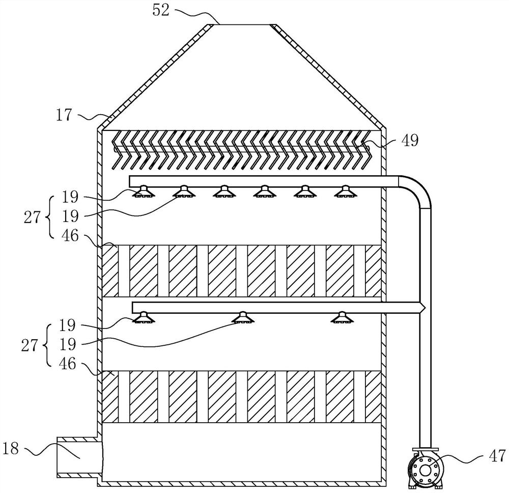
[0043] refer to figure 2The washing inlet 18 is located on ...

Example Embodiment

[0062] Example 2

[0063] refer to Figure 8 The difference between embodiment 2 and embodiment 1 is that the discharge port 5 and the feed port 4 of the adsorption tower 1 form a closed loop, and the second discharge port 10 and the second feed port 9 of the second adsorption tower 6 Also form closed loop, two closed loops are connected with vacuum pump 13 jointly by pipeline, and the outlet of vacuum pump 13 is connected with condenser 14, and vacuum pump 13 can reduce the pressure drop in adsorption tower 1 and the second adsorption tower 6, utilizes step-down desorption The principle of further improving the desorption effect.

[0064] refer to Figure 8 , the closed circuit formed by the discharge port 5 and the feed port 4, and the closed circuit formed by the second discharge port 10 and the second feed port 9 are jointly connected with an emergency pipeline 15, and the emergency pipeline 15 communicates with the inlet of the blower fan 35, An emergency valve 16 is c...


PUM


Abstract

The invention relates to the field of environmental protection, and especially relates to a treatment device for treating waste gas containing dichloroethane. The treatment device comprises an adsorption tower, an adsorbent is arranged in the adsorption tower, and the adsorption tower is provided with a gas inlet and a gas outlet for conveying waste gas; a material inlet and a material outlet which are used for conveying a desorption agent are formed in the adsorption tower, the material inlet is connected with a heating device, the gas inlet is connected with a gas inlet valve, and the material inlet is connected with a feeding valve; the device further comprises a second adsorption tower, the adsorbent is arranged in the second adsorption tower, a second gas inlet and a second gas outlet which are used for conveying waste gas are formed in the second adsorption tower, a second material inlet and a second material outlet which are used for conveying the desorption agent are further formed in the second adsorption tower, and the second material outlet is connected with the heating device; and the second gas inlet is connected with a second gas inlet valve, and the second material inlet is connected with a second feeding valve. The device has the effect of improving the working efficiency.

Description

technical field [0001] The application relates to the field of environmental protection, in particular to a treatment device for treating waste gas containing dichloroethane. Background technique [0002] Pesticides refer to various chemical substances used to prevent and control diseases, insects, grasses, rats and other harmful organisms in agricultural and forestry crops, and to regulate plant growth. With the increasing interference of human activities on the earth's natural resources, extreme weather such as drought and high temperature has also been increasing in recent years, the demand for pesticides is increasing, and the scale of agricultural production is also increasing. During the production process of pesticides, a kind of dichloroethane will be produced. Dichloroethane is a widely used industrial solvent with certain utilization value, and direct discharge will pollute the atmosphere, so it needs to be collected and recycled. [0003] In order to recycle dich...

Claims


Application Information

Patent Timeline
IPC IPC(8): B01D53/04B01D53/18B01D46/12C07C19/045C07C17/389C07C17/38
CPCB01D53/04B01D53/18B01D46/12C07C17/38C07C17/389B01D2253/102B01D2257/2064B01D2259/4009B01D46/62
Inventor 周猛史满良费凡黄倩
Owner 江阴联众环保工程有限公司
Why Eureka
Try Eureka