
Sampling device for regularly detecting microorganisms

A sampling device and microbial technology, applied in the direction of biological material sampling methods, biochemical equipment and methods, biochemical instruments, etc., can solve the problems of non-reusable, waste of resources, etc., to reduce the risk of pollution, high work efficiency, improve The effect of sampling efficiency

Pending Publication Date: 2021-06-15
CHONGQING THREE GORGES UNIV
View PDF0 Cites 0 Cited by
  • Summary
  • Abstract
  • Description
  • Claims
  • Application Information

AI Technical Summary

Problems solved by technology

However, the syringes in the prior art are all disposable plastic materials, which cannot be reused, resulting in waste of resources

Method used


Image

  • Sampling device for regularly detecting microorganisms
  • Sampling device for regularly detecting microorganisms
  • Sampling device for regularly detecting microorganisms

Examples


Embodiment 1

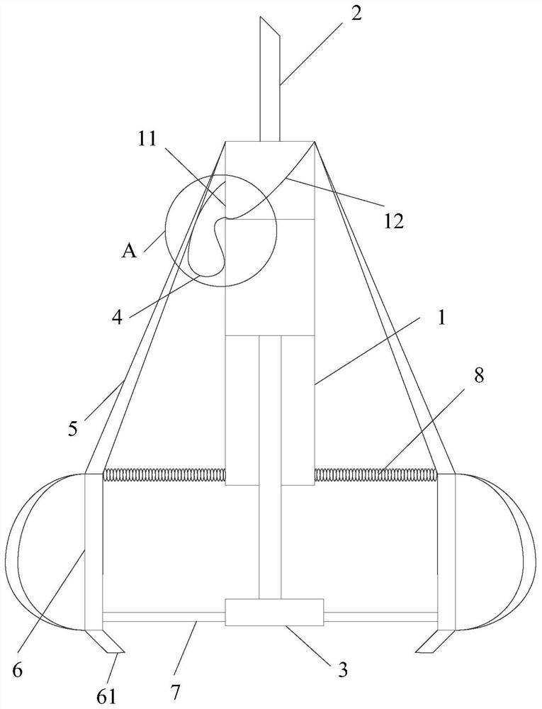
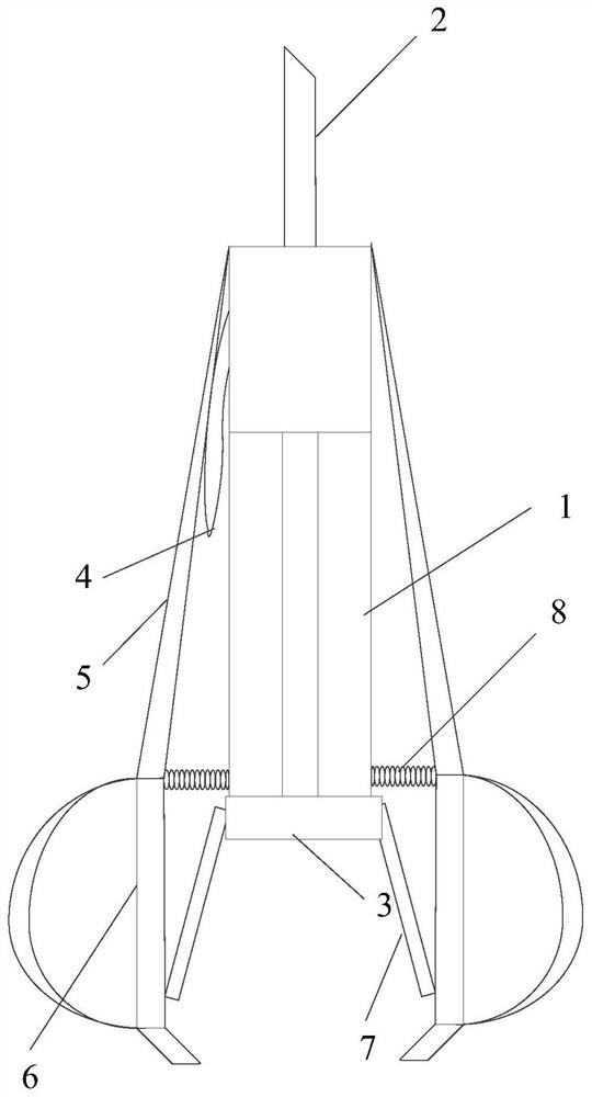
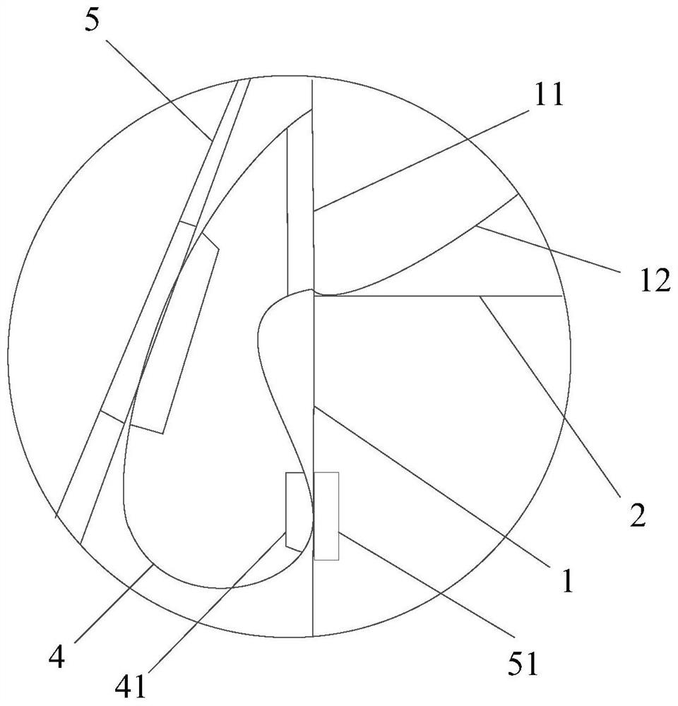
[0036] This embodiment provides a sampling device for periodic detection of microorganisms, including an injection tube 1, the head end of the injection tube 1 is connected with a detachable needle 2, and the injection tube 1 is made of a steel pipe, a ceramic tube or a transparent glass tube. The needle 2 is used for direct contact with the microbial sample liquid. There is a push rod 3 inside the injection tube 1. Push the push rod 3 in the direction of the needle 2 to discharge the air in the injection tube 1, and then pull the push rod 3 to the outside of the injection tube 1. , the microbial sample liquid enters the interior of the injection tube 1, and the side wall of the injection tube 1 is provided with a liquid separation hole 11 at 1-4 cm from the tail end of the needle 2, and a sampling bag 4 is detachably connected to the liquid separation hole 11. 4 is located outside the injection tube 1, and the outside of the injection tube 1 is provided with a extrusion assemb...

Embodiment 2

[0044] A sampling device for periodic detection of microorganisms, basically the same structure as in Example 1, the difference is that see Figure 5 , in order to reduce the work of cleaning the instrument and improve the utilization rate of the instrument, the present invention also includes a head end installation sleeve 9 and a tail end installation sleeve 91. Externally, one end of the pressure plate 5 is rotatably connected to the head-end mounting sleeve 9 instead of being mounted on the injection tube 1, the tail-end mounting sleeve 91 is sleeved and clamped on the tail end of the push rod 3, and the other end of the pressure plate 5 is rotatably connected to the The tail end is installed on the sleeve 91, but not on the push rod 3. Before sampling, install the head end installation sleeve 9 and the tail end installation sleeve 91 according to Figure 5 The shown structure is installed in the corresponding position, and then samples are taken according to the working ...


PUM


Abstract

The invention belongs to the technical field of biological experiment equipment, and particularly relates to a sampling device for regularly detecting microorganisms, which comprises an injection tube made of a cleanable material, a needle head communicated with and detachably arranged at the head end of the injection tube; a push rod arranged in the injection tube, a sampling bag detachably sleeved on a liquid separation hole which is formed in the position, close to the needle head, of the side wall of the injection tube, and extrusion assemblies comprising pressing plates, handles and movable rods, the number of the extrusion assemblies is at least two, the extrusion assemblies are evenly distributed around the outer portion of the injection tube, and the pressing plate of one extrusion assembly can make contact with the sampling bag. According to the device, ear washing bulbs are not needed in the whole sampling process, the taken microorganism sample liquid is directly stored in the sampling bag and does not need to be transferred again, and the risk of microorganism sample liquid pollution is reduced.

Description

technical field [0001] The invention belongs to the technical field of biological experiment equipment, in particular to a sampling device for periodic detection of microorganisms. Background technique [0002] During the liquid culture of microorganisms, it is necessary to take samples regularly to detect the concentration of microorganisms or target substances in the culture liquid at different culture times. Since microorganisms need to continue to be cultured after sampling, in order to prevent contamination, the sampling process requires as little time as possible, and try to operate in a sterile environment near the flame of the alcohol lamp. The prior art sampling devices are pipettes or syringes. When the pipette absorbs the liquid, the operator needs to hold the ear wash ball in one hand and the pipette in the other, and also needs a test tube containing the microbial sample liquid, in order to ensure that the culture bottle containing the microbial culture liquid ...

Claims


Application Information

Patent Timeline
IPC IPC(8): C12M1/26
CPCC12M33/04Y02A50/30
Inventor 黄倩黄珊
Owner CHONGQING THREE GORGES UNIV
Learn More