
Off-axis MEMS micro-mirror and preparation method thereof

A technology of the first micro-mirror and micro-mirror, applied in the field of micro-electromechanical, can solve the problems of difficulty in two-way driving signals, difficulty in synchronizing sending and receiving of lidar systems, differences in driving frequency, angle, and phase difference, etc., to prevent short circuits, reduce The effect of tape-out cost and process error reduction

Active Publication Date: 2021-06-15
无锡微视传感科技有限公司
View PDF6 Cites 1 Cited by
  • Summary
  • Abstract
  • Description
  • Claims
  • Application Information

AI Technical Summary

Problems solved by technology

[0002] Lidar mainly includes two schemes: off-axis and coaxial. Compared with the coaxial scheme, the advantage of the off-axis scheme is that the transmitting system and the receiving system are separated, the stray light in the system is less, and the detection ability is strong. However, the traditional off-axis dual MEMS micromirror usually uses two completely separated micromirrors, and then drives them separately through two driving signals. It is also difficult to achieve complete synchronization and no delay of the driving signal, so it is still difficult to realize the synchronous transmission and reception of the lidar system

Method used


Image

  • Off-axis MEMS micro-mirror and preparation method thereof
  • Off-axis MEMS micro-mirror and preparation method thereof
  • Off-axis MEMS micro-mirror and preparation method thereof

Examples


Embodiment Construction

[0034] The specific embodiments of the present invention will be further described below in conjunction with the accompanying drawings.

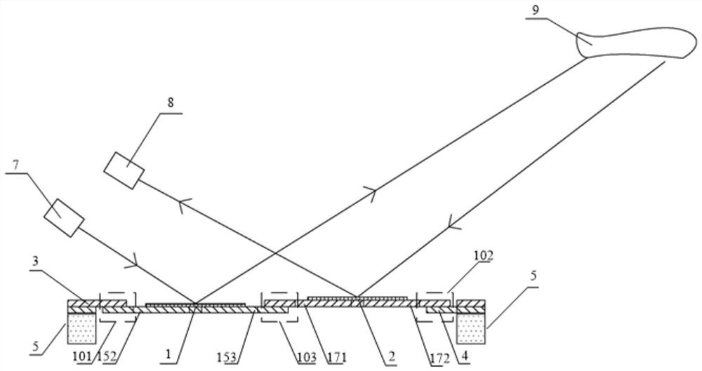
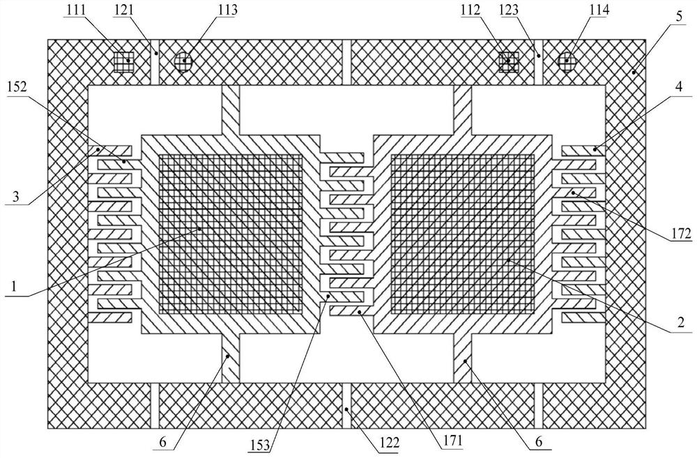
[0035]The application discloses an off-axis MEMS micromirror, combined with figure 1 , figure 2 As shown, it includes a first micromirror 1, a second micromirror 2, a first fixed comb 3, a second fixed comb 4, a driving electrode, a frame 5 and an isolation groove, the first micromirror 1 and the second micromirror 2 The first inner side of the frame 5 is connected by two symmetrical rotating shafts 6, each group of rotating shafts 6 is located on the central axis of the respective micromirror, and the first micromirror 1 and the second micromirror 2 rotate synchronously around the rotating shaft 6. The off-axis MEMS micromirror is used in conjunction with the light source 7 and the detector 8, where the light source 7 provides the incident laser light, the detector 8 receives the reflected laser light, the first micromirror 1 is used for ...


PUM


Abstract

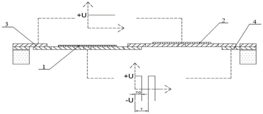
The invention discloses an off-axis MEMS micro-mirror and a preparation method thereof, and relates to the technical field of MEMS. The off-axis MEMS micro-mirror comprises a first micro-mirror, a second micro-mirror, a first fixed comb tooth, a second fixed comb tooth and a driving electrode, the first micro-mirror and the second micro-mirror synchronously rotate by taking a rotating shaft as an axis, the first micro-mirror is used for scanning reflection of incident laser, the second micromirror is used for synchronously receiving reflected laser, and the driving electrode provides driving voltage; a first vertical comb tooth pair, a second vertical comb tooth pair and a third vertical comb tooth pair are formed between the movable comb teeth of the two micro-mirrors and between the movable comb teeth of the two micro-mirrors and the two fixed comb teeth respectively, and the first vertical comb tooth pair and the second vertical comb tooth pair provide clockwise deflection driving force for the first micro-mirror and the second micro-mirror respectively; and a third vertical comb tooth pair provides driving force deflecting in the anticlockwise direction for the first micro-mirror and the second micro-mirror, the two micro-mirrors attract each other in a certain period by manufacturing the potential difference between the vertical comb tooth pair structures, independent control is not needed any more, and the completely same-frequency and same-phase deflection state is achieved.

Description

technical field [0001] The invention relates to the field of microelectromechanical technology, in particular to an off-axis MEMS micromirror and a preparation method thereof. Background technique [0002] Lidar mainly includes two schemes: off-axis and coaxial. Compared with the coaxial scheme, the advantage of the off-axis scheme is that the transmitting system and the receiving system are separated, the stray light in the system is less, and the detection ability is strong. However, the traditional off-axis dual MEMS micromirror usually uses two completely separated micromirrors, and then drives them separately through two driving signals. It is also difficult to achieve complete synchronization and no delay of the driving signal, so it is still difficult to realize the synchronous transmission and reception of the lidar system. Contents of the invention [0003] In response to the above-mentioned problems and technical requirements, the present inventors have proposed...

Claims


Application Information

Patent Timeline
Patent Type & Authority Applications(China)
IPC IPC(8): G02B26/08B81B7/02B81B5/00B81C1/00
CPCG02B26/085B81B7/02B81B5/00B81C1/00198
Inventor 徐乃涛程进孙其梁李宋泽
Owner 无锡微视传感科技有限公司
Learn More