Supercharge Your Innovation With Domain-Expert AI Agents!

Microphone flexible circuit board and manufacturing method thereof

A technology of flexible circuit boards and manufacturing methods, which is applied in the fields of printed circuit manufacturing, circuit devices, printed circuits, etc., can solve problems such as unfavorable yield rate, small sound transmission holes, and irregularities, so as to improve yield rate and use reliability , Improve the sound transmission effect and ensure the effect of acoustic performance

Inactive Publication Date: 2021-06-15
苏州维信电子有限公司
View PDF6 Cites 0 Cited by
  • Summary
  • Abstract
  • Description
  • Claims
  • Application Information

AI Technical Summary

Problems solved by technology

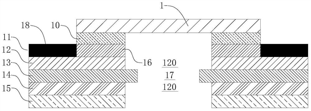
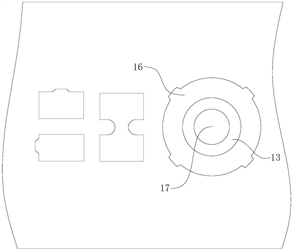
[0004] The flexible circuit board with the above-mentioned structure has the following disadvantages: First, the diameter of the sound hole on the flexible circuit board usually reaches 1mm. performance; secondly, the sound transmission hole on the base layer 13 is made by a punching process, and the burrs produced by punching will affect the welding of the flexible circuit board and the microphone element, and will also have an impact on the performance of the subsequent microphone, and the sound transmission hole 17 and the The avoidance hole 120 has the requirement of concentricity. The accuracy of the punching hole of the ordinary mold is about 2mil. At the same time, the cumulative expansion and contraction of the flexible board will cause punching offset, resulting in smaller and irregular sound transmission holes, resulting in defective products. , is not conducive to improving the yield

Method used


Image

  • Microphone flexible circuit board and manufacturing method thereof
  • Microphone flexible circuit board and manufacturing method thereof
  • Microphone flexible circuit board and manufacturing method thereof

Examples


Embodiment Construction

[0051] In order to make the above purpose, features and advantages of the present application more obvious and understandable, the specific implementation manners of the present application will be described in detail below in conjunction with the accompanying drawings. It should be understood that the specific embodiments described here are only used to explain the present application, but not to limit the present application. In addition, it should be noted that, for the convenience of description, only some structures related to the present application are shown in the drawings but not all structures. Based on the embodiments in this application, all other embodiments obtained by persons of ordinary skill in the art without making creative efforts belong to the scope of protection of this application.

[0052]The terms "comprising" and "having" and any variations thereof in this application are intended to cover a non-exclusive inclusion. For example, a process, method, sy...


PUM

PropertyMeasurementUnit
Diameteraaaaaaaaaa

Abstract

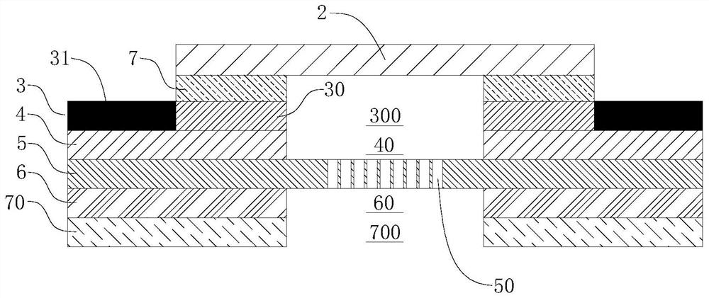
The invention discloses a microphone flexible circuit board and a manufacturing method thereof. The microphone flexible circuit board comprises a base layer (5), a first copper layer (4), a bonding pad layer (3) and a microphone (2); a through hole group is formed in the base layer (5), and the through hole group comprises a plurality of through holes (50); the first copper layer (4) is arranged on the surface of one side of the base layer (5) and is provided with a first avoiding hole (40) for avoiding the through hole group; the bonding pad layer (3) comprises a solder mask (31) and an annular bonding pad (30) which are arranged on the first copper layer (4), and a center hole (300) of the annular bonding pad (30) is corresponding to the first avoiding hole (40); and the microphone (2) is connected to the annular pad (30). According to the microphone flexible circuit board and the manufacturing method thereof, the plurality of dense through holes are formed to form sound transmission holes, so that foreign matters can be effectively prevented from passing through the through holes, and the acoustic performance and the use performance of a microphone are ensured.

Description

technical field [0001] The present application relates to the technical field of flexible circuit boards, in particular to a microphone flexible circuit board and a manufacturing method thereof. Background technique [0002] Microphone (microphone), the scientific name is a microphone, also known as a microphone, a microphone. It is an energy conversion device that converts sound signals into electrical signals. According to the principle, it is classified into moving coil, capacitive, electret and silicon micro microphones, as well as liquid microphones and laser microphones. [0003] At present, most electronic products on the market, such as smart phones and computers, use relatively advanced silicon microphones (MEMS Microphone) for the microphones inside. In electronics, microphones are usually soldered to a flex circuit board. Such as figure 1 and figure 2 as shown, figure 1 A cross-sectional structure diagram of a flexible circuit board in the prior art is shown...

Claims


Application Information

Patent Timeline
IPC IPC(8): H05K1/02H05K1/18H05K3/00B81B7/02
CPCH05K1/0213H05K1/0283H05K1/181H05K3/0026B81B7/02B81B2201/0257
Inventor 李庆贺燕
Owner 苏州维信电子有限公司
Features
  • R&D
  • Intellectual Property
  • Life Sciences
  • Materials
  • Tech Scout
  • Unparalleled Data Quality
  • Higher Quality Content
  • 60% Fewer Hallucinations
Learn More