BIM-based road compaction synchronous monitoring and feedback control system

A feedback control system, real-time monitoring technology, applied in hardware monitoring, database management system, image data processing and other directions, can solve the problems of limited detection points, detection time lag, lack of real-time performance, etc., to improve detection and control level, reduce Human decision-making cost and error, the effect of continuous detection

Pending Publication Date: 2021-06-18
SOUTHEAST UNIV
View PDF0 Cites 3 Cited by
  • Summary
  • Abstract
  • Description
  • Claims
  • Application Information

AI Technical Summary

Problems solved by technology

[0006] Aiming at the problems that the compaction quality detection technology in existing road construction projects has limited detection points, detection time lag, lack of real-time feedback of quality detection results, and low level of feedback form visualization, the present invention provides a BIM-based road The compaction synchronous monitoring and feedback control system, based on the continuous compaction control technology research, uses the powerful 3D visualization capability of BIM technology to perform 3D synchronous visual simulation of the road compaction process and compaction state, and realizes the compaction data and compaction trajectory. , the number of compaction times, and the real-time monitoring and calculation analysis of the compaction quality distribution status, and at the same time establish a compaction quality feedback and control system to realize automatic feedback adjustment and control of the working parameters of the compaction machine to ensure that the compaction operation achieves the best compaction real effect

Method used


Image

  • BIM-based road compaction synchronous monitoring and feedback control system
  • BIM-based road compaction synchronous monitoring and feedback control system
  • BIM-based road compaction synchronous monitoring and feedback control system

Examples


Embodiment 1

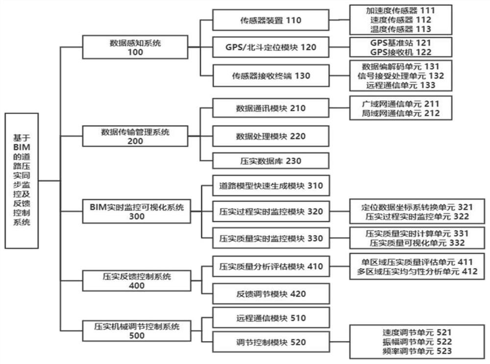
[0049] attached figure 1 A schematic structural diagram of a BIM-based road compaction synchronous monitoring and feedback control system provided by Embodiment 1 of the present invention, including the following components: data perception system 100, data transmission management system 200, and BIM real-time visual monitoring system 300 , a compaction feedback control system 400 , and a compaction machinery adjustment control system 500 .

[0050] as attached figure 1 As shown, the data sensing system 100 includes a sensor device 110, a GPS / Beidou positioning module 120 and a sensor receiving terminal 130. The system is deployed on a single road roller for collecting real-time compaction data information.

[0051] In this embodiment, the on-site compaction data information in the road compaction process is collected in real time by the sensor device 110, which includes: the real-time vertical vibration acceleration response signal of the road roller collected by the acceler...

Embodiment 2

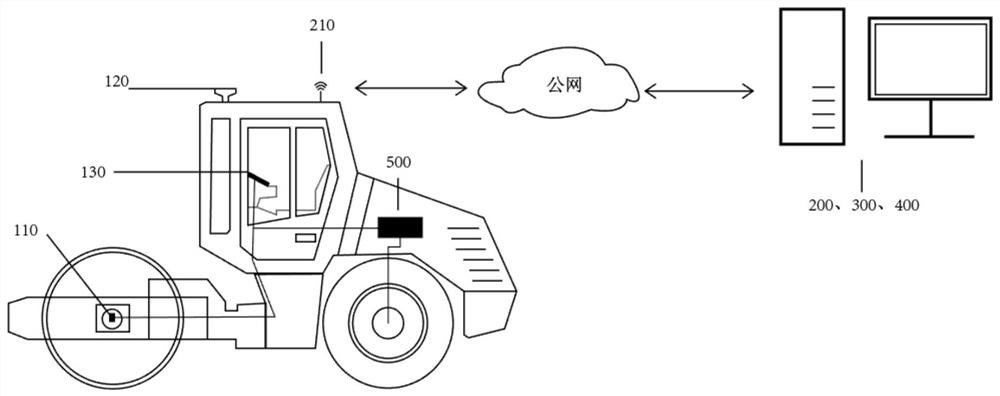
[0066] Embodiment 2 of the present invention provides a schematic diagram of a deployment scheme of a BIM road compaction synchronous monitoring and feedback control system, as shown in the attached figure 2 shown. The deployment scheme relies on a BIM-based road compaction synchronous monitoring and feedback system, which adopts the BIM-based road compaction synchronous monitoring and feedback control system in the first embodiment above.

[0067] as attached figure 2 Shown is a schematic diagram of the deployment of each system module. The data sensing system 100 is deployed and installed on a single road roller. The system includes: a sensor device 110 , a GPS / Beidou positioning module 120 , and a sensor receiving terminal 130 . Among them, the sensor device 110 is installed on the intermediate shaft of the vibrating roller of the road roller, the GPS / BeiDou positioning module 120 is installed on the top of the road roller cab, and the sensor receiving terminal 130 is in...

Embodiment 3

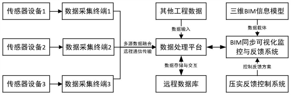
[0071] Embodiment 3 of the present invention provides a flow of real-time data collection, transmission interaction, and feedback adjustment in a working state of the system. The process relies on a BIM-based road compaction synchronous monitoring and feedback system, which adopts the BIM-based road compaction synchronous monitoring and feedback control system in the above-mentioned embodiment 1, and the system deployment method adopts the above-mentioned embodiment 2 System deployment structure.

[0072] as attached figure 2 A schematic diagram of the deployment of each system module is shown. When a single vibratory roller starts to work, the entire data sensing system starts to work, figure 2 The 110 sensor devices in the center integrate three-axis acceleration sensors, speed sensors, and infrared temperature sensors, and will collect the forward speed data of the road roller, the vibration acceleration data of the vibrating wheel, and the temperature data of the road ...


PUM


Abstract

The invention provides a BIM-based road compaction synchronous monitoring and feedback control system. The BIM-based road compaction synchronous monitoring and feedback control system comprises a data sensing system, a data transmission management system, a BIM real-time monitoring visualization system, a compaction feedback control system and a compaction mechanical adjustment control system. According to the invention, a three-dimensional synchronous simulation monitoring and feedback control system is established based on the research of a continuous compaction control technology and by virtue of the powerful three-dimensional visualization capability of a BIM technology, real-time monitoring and calculation analysis of compaction data, a compaction track, compaction times and a compaction quality distribution state are realized; meanwhile, a compaction quality feedback and control system is established, automatic feedback adjustment control of working parameters of the compaction machinery is realized; fine construction of roads is powerfully promoted; the construction information interaction efficiency is improved; and the final quality of compaction construction is ensured.

Description

technical field [0001] The invention relates to the technical field of road construction intelligent construction, and in particular relates to a BIM-based road compaction synchronous monitoring and feedback control system. Background technique [0002] One of the most important links in the compaction process in road construction. Engineering practice and experimental research at home and abroad have already proved that construction machinery must be used for careful compaction during the construction of the subgrade pavement structure layer, so as to improve the structure of the subgrade and pavement. The overall strength of the layer and the pavement increases its stability, so as to reduce or even avoid various early damage phenomena that may occur on the pavement, thereby greatly improving the performance and service life of the pavement. In order to ensure that the road compaction quality meets the specified requirements, it is an important means to monitor the compact...

Claims


Application Information

Patent Timeline
Patent Type & Authority Applications(China)
IPC IPC(8): G06F11/30G06F16/25G06T17/10
CPCG06F11/3006G06T17/10G06F16/252
Inventor 马涛韩涛方周马源
Owner SOUTHEAST UNIV
Why Eureka
Try Eureka