Giant magnetostrictive vibration source

A technology of giant magnetostrictive and magnetostrictive materials, applied in piezoelectric effect/electrostrictive or magnetostrictive motors, electrical components, generators/motors, etc., can solve power plant or substation outage, construction period Long, large engineering volume and other issues, to achieve the effect of improved energy conversion efficiency and excellent mechanical properties

Pending Publication Date: 2021-06-18
CHONGQING CUILU DETECTION TECH CO LTD
View PDF0 Cites 0 Cited by
  • Summary
  • Abstract
  • Description
  • Claims
  • Application Information

AI Technical Summary

Problems solved by technology

There are several problems in this detection method as follows: ①The amount of engineering is large
If the grounding grid of the power plant or substation is detected by excavation, due to the long construction period, the power plant or substation will be shut down, which will have a wide range of impacts
③The test result is inaccurate

Method used


Image

  • Giant magnetostrictive vibration source
  • Giant magnetostrictive vibration source
  • Giant magnetostrictive vibration source

Examples


Embodiment Construction

[0040] The specific implementation manner and working principle of the present invention will be further described in detail below in conjunction with the accompanying drawings.

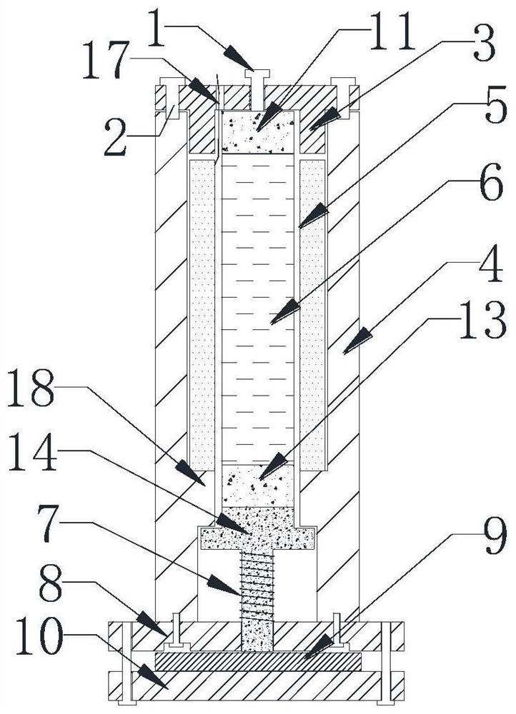
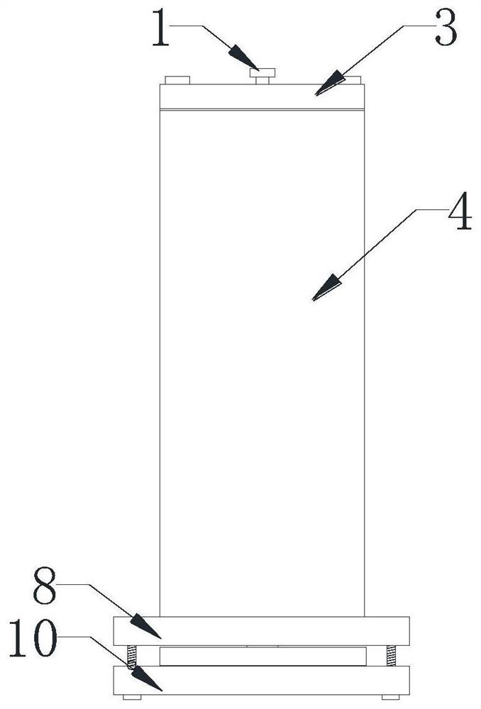
[0041] to combine Figure 1-3 It can be seen that a giant magnetostrictive vibration source includes an excitation coil 5, a magnetostrictive material rod 6 is arranged in the axial direction in the excitation coil 5, and elastic Vibration output member 14, the end of the magnetostrictive material rod 6 away from the telescopic end is provided with a limit end cap 3, when the magnetostrictive material rod 6 is deformed along the direction of the telescopic end under the action of the excitation coil 5, the The detection end of the elastic vibration output member 14 moves along its deformation direction.

[0042] In this embodiment, the magnetostrictive material rod 6 is made of FeGallium alloy. The magnetostrictive material rod 6 adopts Fe83Ga17 alloy.

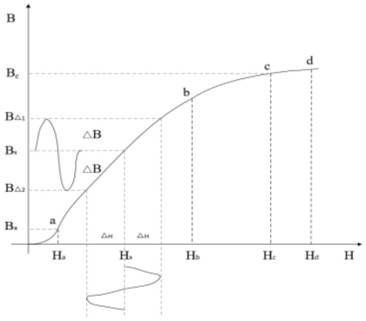
[0043] Among them, the magnetostrictive mat...


PUM


Abstract

The invention discloses a giant magnetostrictive vibration source which comprises an exciting coil (5), a magnetostrictive material rod (6) is arranged in the exciting coil (5) in the axial direction, an elastic vibration output piece (14) is arranged in the telescopic end direction of the magnetostrictive material rod (6), and a limiting end cover (3) is arranged at the end, away from the telescopic end, of the magnetostrictive material rod (6), when the magnetostrictive material rod (6) deforms in the direction of the telescopic end under the action of the excitation coil (5), the detection end of the elastic vibration output piece (14) moves in the deformation direction of the elastic vibration output piece (14). By transmitting a step excitation signal to the excitation coil, the giant magnetostrictive material rod is triggered to excite so as to generate vibration.

Description

technical field [0001] The invention relates to the technical field of elastic wave non-destructive testing, in particular to a giant magnetostrictive vibration source. Background technique [0002] For all kinds of metal devices and equipment that have been fixed and installed, when detecting their damage, corrosion, etc., the method of dismantling or taking them out is generally used for direct observation. However, for a large amount of engineering or expensive equipment, the energy or manpower consumed for dismantling or taking it out is extremely high, and it is not suitable to take it out for inspection. [0003] For example, the grounding grid, which exists in every link of the power system, is an extremely important part of the power system. Due to the limitation of economic conditions, a large amount of steel is used in my country's grounding grid. The traditional grounding grid generally uses galvanized flat steel. Recently, copper-clad flat steel has also been us...

Claims


Application Information

Patent Timeline
IPC IPC(8): H02N2/02
CPCH02N2/026
Inventor 廖先彭开桃刘人宽付志红王维刘龙欢王浩文
Owner CHONGQING CUILU DETECTION TECH CO LTD
Why Eureka
Try Eureka